HRX-OM-O021
Chapter 5 Display and setting of various functions
HRS Series 5.15 Alarm customize function
5-43
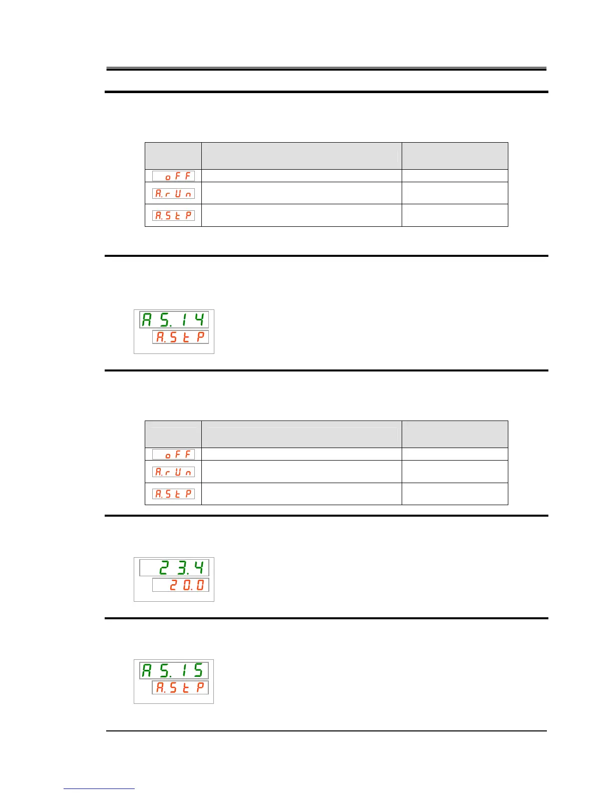
25. Select the changing of contact input signal 1 detection from the table below with [▲]
key or [▼] key, and confirm by pressing “SEL”.
Table 5.15-14 List of set value
Set value Explanation
Initial value
(Default setting)
This alarm signal is not detected.
Operation continues when this alarm signal is
generated.
Operation is stopped when this alarm signal is
generated.
○
Changing of Contact input signal 2 detection Setting and checking
26. Press the [SEL] key once.
The set screen of the changing of contact input signal 2 detection is displayed on the
digital display.
PV
SV
27. Select the changing of contact input signal 2 detection from the table below with [▲]
key or [▼] key, and confirm by pressing “SEL”.
Table 5.15-15 List of set value
Set value Explanation
Initial value
(Default setting)
This alarm signal is not detected.
Operation continues when this alarm signal is
generated.
Operation is stopped when this alarm signal is
generated.
○
28. Press the [MENU] key once.
Return to the main screen (screen displaying the circulating fluid temperature).
PV
SV
Changing of DC line fuse cut Setting and checking
29. Press the [SEL] key once.
The set screen of the changing of DC line fuse cut is displayed on the digital display.
PV
SV
 Loading...


