EasyManua.ls Logo

SMC Networks IP8001 Series User Manual

Default Icon
89 pages
To Next Page IconTo Next Page
Page #1 background imageLoading...
Page #1 background image
No. IP8S-OM00009-B
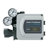
SMART POSITIONER (LEVER TYPE)
PRODUCT NAME
IP8001 Series
MODEL/ Series

Table of Contents

Questions and Answers:

SMC Networks IP8001 Series Specifications

General IconGeneral
Input Signal4-20 mA
TypeElectro-pneumatic
Supply Pressure1.4-7 bar
ProtectionIP65
Ambient Temperature-20°C ~ +80°C
Housing MaterialAluminum

Summary

Safety Instructions

Hazard Levels and User Responsibilities

Explains hazard levels, user responsibility, and need for trained personnel.

Special Conditions, Warranty, and Compliance

Covers precautions for special conditions, warranty terms, and compliance requirements.

Introduction and Specifications

Parameter Settings List

Workflow of IP8001 Positioner Setup

Operating Principle

Mechanical Installation

Mounting Procedures

Provides instructions and warnings for securely mounting the positioner onto an actuator.

Feedback Lever and Piping Connections

Details feedback lever connection and piping for air supply.

Electrical Wiring and ATEX Safety

Electrical Wiring Procedures

Provides crucial safety warnings and procedures for electrical wiring.

ATEX Explosion Protection and Barriers

Covers safety for explosion-protected environments and associated barriers.

Component Description and LCD Display

Initial Adjustment and Calibration

Setup Parameters and Calibration Procedures

Guides through initial parameter changes, feedback lever check, and auto calibration.

Input Current Calibration

Details the process for calibrating input current values.

Mode Operation

Mode Change on LCD

Explains how to switch between Auto, Manual, and Parameter modes.

Auto and Manual Mode Usage

Describes using the positioner in automatic and manual control modes.

Parameter Code Detail

Actuator, Direction, and Split Range Settings

Covers actuator type, direction, and split range settings.

Zero/Span, PID, and Alarm Settings

Details zero/span, PID, and alarm settings.

Analog Output and Calibration Functions

Explains analog output and various calibration functions.

Parameter Setting Procedures

Basic Parameter Procedures

Guides setting actuator direction, split range, and zero/span.

Advanced Parameter Procedures

Covers forced close/open, dead band, and valve characteristics.

PID, Alarm, and Output Configuration Procedures

Details PID, alarm, and analog output configuration procedures.

Improved Controllability

Maintenance and Operational Precautions

Maintenance and Check Procedures

Outlines procedures for routine maintenance and checking the positioner.

Handling, Air Supply, and Environment

Provides handling advice, air supply requirements, and environmental considerations.

Troubleshooting and Error Codes

Troubleshooting Common Issues

Lists common problems, their causes, and countermeasures.

Error and Check Code Lists

Details specific error codes and check codes with solutions.

How to Order

Drawings and Parts List

Related product manuals