Home
SMC Networks
Valve Positioners
IP8001 Series
Page 50
SMC Networks IP8001 Series - Page 50
89 pages
Manual
To Next Page
To Next Page
To Previous Page
To Previous Page
Loading...
No.IP8S-OM00
009
49
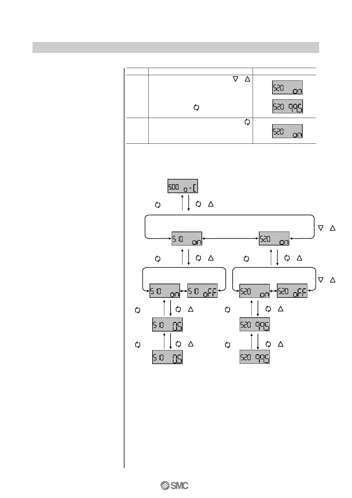
Procedure
LCD display
5
Press UP
or
DOW
N
button (
)
to
set
upper
value
within
90.0
to
100.0%
by
(520)
as
lower
value
setting
of
clause
4.
H
old
down
the
mode butt
on (
) for 1sec.
or longer
for 2 times
with some inter
val.
6
Hold
down
the
mode
button
(
)
again for 1sec.
or longer to
set.
or
Lower limit setting
(
%
)
Upper limit setting
(
%
)
or
Mo
de button
(
)
≧
1s
Set button
+
(
)
≧
1s
Mode button
(
)
≧
1s
Set button
+
(
)
≧
1s
Mode button
(
)
≧
1s
Set button
+
(
)
≧
1s
Mode button
(
)
≧
1s
Set button
+
(
)
≧
1s
Mode button
(
)
≧
1s
Set button
+
(
)
≧
1s
or
Mode button
(
)
≧
1s
Set button
+
(
)
≧
1s
Mode button
(
)
≧
1s
Set button
+
(
)
≧
1s
Fig.38
49
51
Table of Contents
Main Page
Table of Contents
2
Safety Instructions
4
Introduction
6
Specifications
6
Parameter Settings List
8
Workflow of IP8001 Positioner Setup
9
Operating Principle
10
Mounting
11
Example of Mounting on Actuator
11
Connection of Feedback Lever
12
Feedback Lever Unit
12
Body Cover Unit
12
Piping
13
Selecting OUT1/OUT2 Port
13
Piping of Double Acting Actuator
13
Piping Layout
14
Electrical Wiring
15
Without Output Function (IP8001-0*0, IP8001-0*3)
15
With Output Function (IP8001-0*2, 52-IP8001-0*4)
15
Electrical Wiring
16
ATEX Intrinsic Safety Type of Explosion Protected Construction
17
Explosion Protected Construction Rate
17
Wiring
17
Barrier
18
Description of Components
19
Contents of LCD Display
19
Initial Adjustment
20
Change of Parameters for Initial Operation
20
Selection of Calibration Mode
20
Check Angle of Feedback Lever
21
Simple Balance Current Adjustment
23
Calibration
24
Input Current Calibration
27
Mode Change on LCD
28
Mode Change
28
Parameter Mode Functioning in Manual Mode
28
Reflection of Changed Content in Parameter Mode
28
Auto Mode Operation
29
Auto Mode
29
Display Switching Method at Auto Mode
29
Manual Mode Operation
29
Setting Parameters
30
Parameter Code
30
Parameter Code Detail
31
How to Change Values
42
Parameter Setting Procedure
43
Parameter Setting Default Value List
74
Operation Procedure Panel on PCB Cover
75
Improved Controllability
75
Maintenance and Check
76
Caution on Handling
77
Operation
77
Handling
78
Air Supply
78
Environment
78
Troubleshooting, Error Code and Check Code
79
Troubleshooting
79
Error Code List
81
Check Code List
83
How to Order
84
Drawing
85
Related product manuals
SMC Networks IP8101 Series
85 pages
 Loading...