MENTOR 12 USER’S MANUAL SECTION 3: ADVANCED CONTROL – Page 46
and that indicates their state (red they are active and white
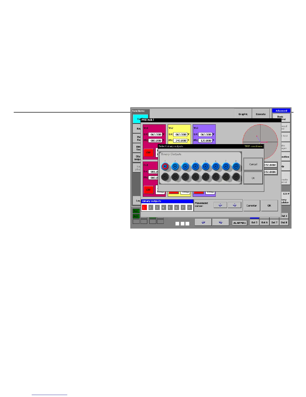
deactivated). A window appears when this rectangle is
pressed displaying the binary outputs as they appear on the
equipment terminal panel. If you press the blue terminal of
each one of them, you select the relative output as active, as
shown in the picture below. Bear in mind that the state of the
output (active or deactivated) depends on how the output is
configured in CONFIGURATION (NO or NC)
The TRIP signal that stops the execution of the function can
also be configured in any of them, by combining the twelve
available binary inputs in OR or AND logic. This condition
can be selected by pressing the white-colored button marked
“TRIP” on the configuration screen.
 Loading...

