MENTOR 12 USER’S MANUAL SECTION 2: BASIC CONTROL – Page 23
Description of source controls
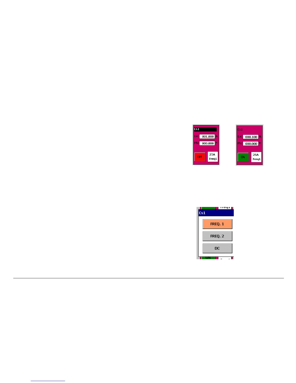
Source with
output
ACTIVATED
and SELECTED
Default source with
deactivated,
independent output
(NOT SELECTED)
The controls of a power output source are described below.
The figure shows what the control of a power output source looks like, before it has
been manipulated in any way, which is, in default conditions (see Configuration). We
can see the following controls and tags:
• Cs1:
This indicates the type of Cs (Current Source) source and its number
(1).
There can be up to 6 current sources, depending on the equipment
configuration (Cs1 … Cs6).
When pressed, the background color changes to BLACK meaning that the
source has been SELECTED.
The following tags can be found, indicating the different types and numbers of
sources available, which are, apart from the current sources described:
• Vs…n: This indicates that it is a Voltage Source. There can be up to 6 at the
same time depending on the configuration.
Source in Frequency BUS
selection mode
• Ll…n: This indicates that the output source used is a Low Level Output.
There can be up to 6 outputs at the same time, depending on the
configuration of the power sources (See Configuration Section for greater
detail). They tally with the output of the Connectors marked LL OUT from 1 –
3 and from 4 – 6.
• Lv xxx.xxx A:
The Lv tag indicates that the value selection made in the
associated setting window is for SIGNAL LEVEL. The next tag (in this case A
for amperes) indicates the unit of the level selected. This can be A (amperes),
or V (Voltage) and this corresponds with the type of output source. The level
is selected with the resolution and number of available digits indicated
therein.
 Loading...

