MENTOR 12 USER’S MANUAL SECTION 2: BASIC CONTROL – Page 41
System alarms
The Mentor has different alarms that warn the operator when
different systems are not working correctly as soon as they
are activated. They are mainly applied to the equipment
power outputs and are always visible on any of the screens
and/or applications except in the Configuration ones.
When any kind of alarm occurs in an output source, its level
indication window lights up in RED, also deactivating the
On/Off output control.
Furthermore, the button marked as “Alarms” situated on the
bottom of the screen, also lights up in RED.
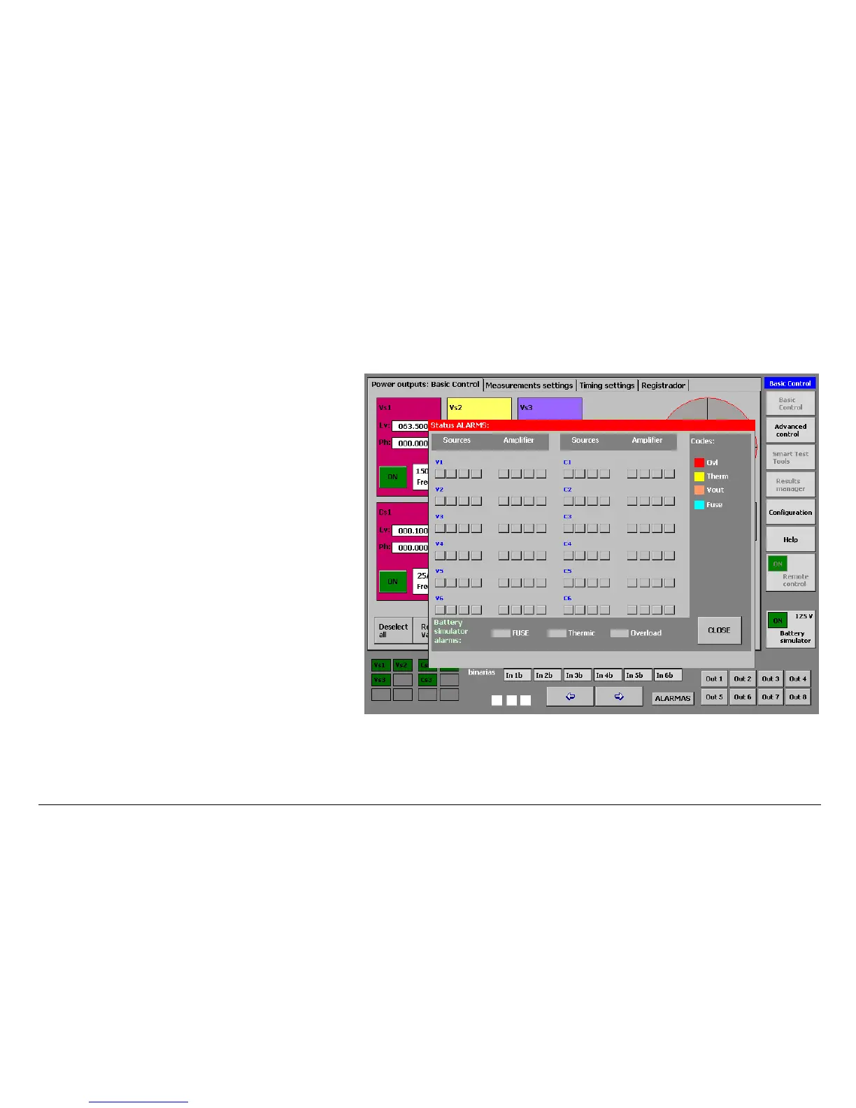
When we press this button a screen appears that indicates
the type of alarm that has occurred and the module where it
has occurred. For this purpose, all the output sources are
divided into one section that corresponds to its Power
Supply Source and another section that corresponds to its
Amplifier.
The following types of alarms can be indicated by the
sy t
•
s em:
OVL.- This means overload of the source affected.
This alarm indicates that the source is being
overloaded, with respect to its maximum power
capacity. In the case of current sources this
generally indicates that their output is open or that the load connected is
excessive for the power and the values selected. In voltage
sources it
indicates that the load is excessive for their power or that there is a short-
 Loading...

