Operation Manual
7
Connecting the PME-500-TR to the breaker
The PME-500-TR connects to the circuit breaker under test by means of four multi-pole
connectors. The first three (Coil Control, Main Contacts and Auxiliary Inputs) are
duplicated with equivalent banana-type connectors in case any of the supplied multi-wire
leads is lost or damaged. Once you have the instrument correctly wired to the breaker, the
rest of the job is greatly simplified. A brief description of these connections follows.
Wiring the Coil Control circuits
WARNING! Auxiliary voltage inside a circuit breaker can reach
250 Vdc. Be sure that auxiliary supply is disconnected before
manipulating the operation coil circuits of the breaker.
This is the most controversial point of connection for new users. The key to proper cabling
is understanding that two internal solid-state PME-500-TR’s contactors are supposed to
control (rather than to provide) the DC supply circuits of both (Trip and Close) coils of the
breaker. Hence, these contactors must be connected in series with their corresponding
coils and polarity must be respected. Look at the diagram in the instrument’s lid. If you are
breaking at the positive side of the breaker’s coils, then connect each black T or C lead
to its corresponding coil and the blue leads to a point coming from the positive side of the
DC supply. Use the opposite color scheme if you are breaking at the negative side of the
coils. This setup will give TRIP/CLOSE control to the PME-500-TR for easier, faster and
more accurate testing.
The multi-pole connector is duplicated so that standard bananas can be used instead
(black corresponds to negative and green to positive).
DC Polarity to the breaker’s coils must be respected in this
cabling procedure or the control actions from the PME-500-TR
will not be performed at all.
Red LED indicators will be lit instantaneously whenever the PME-500-TR completes the
circuits into which these contacts are inserted.
PME-500-TR
8
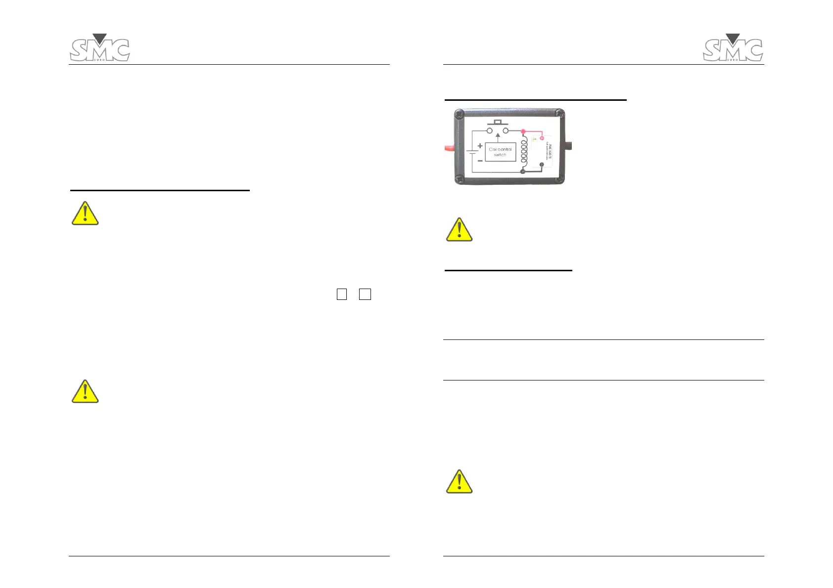
Overvoltage protection diodes
To avoid premature wear due to inductive arcing
across the coil control contacts, most
manufacturers install internal protection diodes in
parallel to the operation coils. If the circuit breaker
that you are testing lacks this protection or you are
not sure about its condition, connect the supplied
diodes directly in parallel to the operation coils,
using the same polarity, as shown in the diode’s
label (view figure).
Failure to do this might cause harmful voltage to develop
inside the PME-500-TR when the coil supply circuit is
interrupted during the testing, which will produce serious
damages that are not covered by the equipment’s warranty.
Wiring Main Contacts
The breaker’s main contacts are wired to the PME-500-TR through this connector. Attach
the red “C” terminals to one side of the poles and the black ones to the other side. Use
order 1, 2 and 3 and colors consistently at each pole. If you use the duplicate 4-mm
connectors, you will have to bridge one side of the three poles to make a common point
and connect it to the “Com.” connector.
IMPORTANT NOTICE: WITH GROUNDED BREAKERS – Time and resistance tests are
not possible while both sides of the breaker are connected to ground. You can keep
only one side connected to ground as long as you use the black banana terminals to
the poles on that side, and the red ones to the free poles.
For timing tests, the PME-500-TR injects a low (100 mA) current through the breaker’s
poles using these leads, in order to detect and record changes in the contact status.
For resistance measurement, a 10 A test current is injected using these wires, and the
voltage drop is measured at the terminals of the contact resistance connector (described
later in this section) that should also be wired to the poles for this purpose.
If you accidentally apply any significant voltage to these leads,
one or more internal fuses might be blown. Should this occur,
refer to the troubleshooting section at the end of this manual
for instructions on fuse replacement.
 Loading...