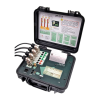
Operation Manual
25
Technical Characteristics
INPUT SECTION
Main Contacts
Number: 3 inputs + common (earth)
Open Circuit Voltage: 10 V Dc maximum
Test current 100 mA maximum
Detected States: Closed (C) (r<30 Ω)
Pre-insertion (R) (30 Ω < r < 10 k Ω
Open (O) (r > 10k Ω)
Auxiliary Inputs
Number: 2 completely isolated binary inputs
Contact Mode Open Circuit Voltage: 5 Vdc
Test current: 20 mA maximum
Voltage Mode: Range: From ±1.5 to ±400 Vdc
Low activation range: ± 1.5 to ± 15 Vdc
High activation range: ± 15 to ± 400 Vdc
PME-500-TR
26
BREAKER OPERATION
Programmable sequences:
Close (C)
Open (O)
Close – Open (C – O)
Open – Close (O – C)
Close – Open – Close (C – O – C)
Open – Close – Open (O –C – O)
Time measurement start signal
Can be selected between:
Coil operation
Auxiliary input 1 ON or OFF
Auxiliary input 2 ON or OFF
Position change at any contact input
Delay up to 18.0 seconds
Command Duration Settings
Close, Open, 1
st
Interval, 2
nd
Interval
10 to 2000 ms (in 10-ms steps)
MEASUREMENT
Time Measurement and Graphical Representation
Graphics window length: Selectable between 100 ms, 200 ms, 400 ms, 800 ms,
1600 ms and 2000 ms
Time resolution: ± 0.1 ms (10 kHz sampling frequency)
Accuracy: ± 0.05 % ± 0.1 ms
Graphics resolution: 0.8 ms per mm

 Loading...