Operation Manual
17
c) If you selected the DELAYED option, the programmed sequence will be issued but
no time data will be recorded before the selected contact activity is detected, or the
specified wait time has elapsed, or 18 seconds later, whichever occurs first.
In any of the above cases, the system’s timer will start exactly when the first programmed
command (Trip or Close) in the test sequence is issued to the breaker. If contacts at the
end of the test are in the expected position, the message Status: Test Done will be
displayed. Otherwise, Status: Error During Test will be displayed instead, so you can
check your connections and settings and try again.
If you have programmed the test sequence to begin with a TRIP operation, ensure that
the breaker is previously placed in its closed position. Reversely, if you are starting with a
CLOSE operation, place the breaker in its open position first. Otherwise, a Status:
Switch Incorrect message will be displayed when the test is attempted. If you have
wired the PME-500-TR’s coil control terminals to the working control circuits of the
breaker, you can issue manual Trip or Close commands to the breaker by touching the
TRIP
or CLOSE buttons at the bottom of this screen accordingly. No
recording will result from the use of these buttons.
Also at the bottom of this window, buttons
and are found. If you are using
the auxiliary inputs to detect the Trigger event, you must set the detection mode
according to the type of signal expected in that input. Press the corresponding button
repeatedly to cycle through Dry Contact, Low Voltage (1.5 to 15 V) and High Voltage
((15 to 400 V) modes while you observe the status LEDs next to the duplicate Aux.1 or
Aux.2 connectors.
Contact Resistance Measurement
Contact resistance measurement is a separate process that you can carry out whenever
the breaker is closed. Also, the appropriate test leads must be in place, naturally. Refer to
the connection instructions at the beginning of this manual for details on proper cabling.
If the breaker is not closed or not properly connected to the
PME-500-TR, or if the built-in battery is exhausted, you will get
a measurement error message, rather than an erroneous
resistance value.
Refer to the troubleshooting section at the end of this manual if you experience contact
resistance measurement problems.
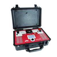
PME-500-TR
18
Error and Status Messages
When you first enter the TEST window, the status line displays the present detection mode
of the Auxiliary inputs #1 and #2 with any of the following messages:
Aux1/2,Volt Mode,Hi: Auxiliary input 1/2 set for high voltage (± 15 Vdc).
Aux1/2,Volt Mode,Lo: Auxiliary input 1/2 set up in low voltage (± 1.5 Vdc).
Aux1,Contact Mode: Auxiliary monitor 1 set up in contact mode.
Aux2,Contact Mode: Auxiliary monitor 2 set up in contact mode.
Following is a list of possible test-related messages:
Error During Test: An error has occurred during the test. Repeat the test.
Switch Incorrect: The initial position of the main contacts make the first test command
execution impossible.
Test In Progress: This message is displayed during the execution of the operation
sequence.
Test Done: Test successfully completed (this does not mean a good breaker’s
condition).
Test Aborted: The user has pressed the START/STOP button a second time.
Switch Close: Circuit breaker closed.
Switch Open: Circuit breaker open
Waiting Trigger: Waiting for the specified trigger event to occur at the selected
auxiliary input.
Switch Cooling: Equipment’s Internal switchgear is cooling down (test temporarily not
allowed).
Switch Open Ovld: When current through the trip coil control circuit reaches 53 Adc a
protective mechanism will automatically cut off.
Switch Close Ovld: When current through the close coil control circuit reaches 53 Adc
a protective mechanism will automatically cut off.
Aux1 Overload: Auxiliary input will switch to voltage mode whenever any significant
voltage is detected.
Aux2 Overload: Auxiliary input will switch to voltage mode whenever any significant
voltage is detected.
 Loading...