Operation Manual
15
pressed in the TEST menu. This is the most commonly used trigger event when
the breaker’s coil DC supply circuits can be set under the control of the PME-
500-TR.
AUX1(ON) or AUX2(ON): After pressing the START/STOP button, the unit will
stay on hold until a voltage appears or a contact is closed at the selected
auxiliary input.
AUX1(OFF), AUX2(OFF): After pressing the START/STOP button, the unit will
stay on hold until any present voltage disappears or the contact is opened at
the selected auxiliary input.
Auxiliary input events are used when the breaker cannot be controlled from
the PME-500-TR for any reason or simply when the user wants the recorded
times to be referenced to an electrical change different from the sending of the
first TRIP or CLOSE command.
DELAYED: Use this option to analyze switchgear that takes more than 2 s. to
complete a maneuver, such as a closing interrupter/breaker combination.
After the first command has been issued to the coil, the data recording can be
delayed until –
o A change is detected at any main contact (“MAIN CNT”)
o A change is detected at any auxiliary contact (“AUX CNT”)
o A change is detected at any contact (“ANY CNT”)
o The time specified in the TRIG. DELAY parameter (see below) is
elapsed (“TIME”)
NOTE: Maximum delay is 18 seconds, regardless the option selected
REC. LEN: The graphics window’s size in milliseconds is stored here. The smaller the size
(shorter time), the higher the detail, or ZOOM effect of the printed graphics will be.
Graphics representation aperture can be selected among 200, 400, 800, 1600 and
2,000 ms. This field can be modified after the test is done to re-print the report for a better
fit as many times as desired. However, once the test is saved into non-volatile memory, the
recorded data will be truncated to the specified length permanently.
DEBOUNCE T: This field specifies the minimum duration for which any recorded state
(closed, open or pre-insertion) must be held in order to be included in the contact times
listing. This filter prevents the timings print area to overflow and can be chosen among 0,
0.5, 1 and 2 ms. Debounce will not affect the graphic representation of the contacts’
states.
TRIG. DELAY: If you selected DELAYED … TIME at the Trigger menu, you can specify
the wait time here, up to 18.0 s. in 0.1 sec. increments.
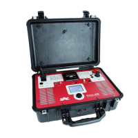
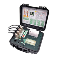
PME-500-TR
16
Test Execution
Time & Coil Current Analysis
This process consists basically of recording what happens inside the breaker in terms of –
Changes in main contacts’ state
Changes at auxiliary inputs.
Evolution of DC current in the operation coils.
The recording duration is 2 seconds, and the above changes are detected and time-
stamped at 10 kHz (10,000 samples per second) resolution for timing and 1 kHz for
currents. This duration spans well beyond the TRIP-CLOSE-TRIP sequence of any breaker.
Warn surrounding people nearby before actuating a medium-
or high-voltage circuit breaker.
Once the PME-500-TR is correctly wired to the breaker and the test conditions are set as
explained above, the test procedure is reduced to a few simple steps:
1) Open the TEST screen by touching the
button.
2) Touch the
button.
During the first 1 -1 ½ seconds the unit will clear the sampling memory, will check the
breaker’s contact positions and will reset the internal counters. This short delay makes new
users think that they have not touched well and usually retry, sometimes causing the
process to be cancelled.
Once the PME-500-TR has completed this short warm-up process, one of the following
will occur:
a) If OPERATION was selected as the Trigger Event in the Test Setup menu, the
programmed sequence will be issued to the breaker, the timer will start and the
recording of data will take place immediately.
b) If you selected any of the AUXiliary inputs as the trigger event, the process will stay
on hold until the specified event takes place at the chosen input. The message
Status: Waiting Trigger will be displayed at this time. If you press the
START/STOP button again now, the process will be cancelled and the message
Status: Test Aborted will be displayed. When the expected event is detected, the
test is initiated.
 Loading...