Operation Manual
9
Using the Auxiliary Inputs
These additional input channels can be used independently for two different purposes:
1) Analyzing the open/close activity of any two contacts inside or related to the circuit
breaker during with the timing test.
2) Detecting contact or voltage changes at any two points inside or related to the
breaker to start the timer and the data recording process. This is called ‘trigger
event’ detection, described in the test setup section.
These inputs are fully isolated from each other and from the earth of the equipment and
have no polarity. Two pairs of LEDs next to the duplicate 4-mm connectors indicate the
mode (dry contact or voltage detection) to which these inputs have been set up as later
described in the Test Menu section. Protection against accidental overvoltage (above 400
V) is provided for these inputs by means of internal fuses. Refer to the troubleshooting
section at the end of this manual for instructions on locating and replacing these fuses.
The auxiliary inputs are commonly used to analyze the breaker’s coil contacts timing with
relationship to the main contacts, but it is also frequent to connect them to some other
points inside the breaker or affected by its operation, like auxiliary contacts or monitoring
points, also for time analysis purposes. However, using these inputs as test initiators is also
a powerful technique when, for example, you cannot drive the breaker from the PTE-500-
TR or you want to refer the time analysis to an electrical event other than the START
command in the instrument. This technique is further described in the Test Execution
section.
Resistance Measurement Connector
As explained before, when resistance measurement is conducted, a 10 A test current is
injected through the main contact connector’s leads and the voltage drop at the contacts
is measured by the leads in this connector.
IMPORTANT NOTICE: WITH GROUNDED BREAKERS – Time and resistance tests are
not possible while both sides of the breaker are connected to ground. You can keep
only one side connected to ground as long as you use the black banana terminals to
the poles on that side, and the red ones to the free poles.
This 4-wire method provides adequate accuracy as long as connections are made firmly
and in the correct order, which is the pole’s contact inside the Res. Measure points and all
this inside the Contacts connections. Phase order (1, 2, 3) and polarity (Red, Black) must
also be consistent between the Main Contact lead set and the Resistance Measurement
terminal set. If you connect the main Contacts leads in between the Res. Measure leads,
you will get a wrong, useless resistance value because this will include the resistance of the
Contacts test leads’ connections.
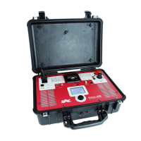
PME-500-TR
10
Using the optional PME-RESC fast clamps
These clamps may save time and connection errors, as you will have to connect only 6
clamps instead of 12 for timing tests and contact measurement. Plug the black C1 and R1
terminals into a black PME-RESC clamp. Then, do the same with black C2/R2, C3/R3
terminals, and finally use the red PME-RESC clamps in the same way for the remaining red
terminals. You can now connect the red clamps to one side of each pole and the black
ones to the other side, observing the 1-2-3 phase correspondence.
IMPORTANT: Use only the PME-RESC clamps for this simplified connection method,
as these clamps’ arms are isolated from each other. The use of regular clamps with
this method will produce erroneous contact resistance measurements.
Beware that the measured value will correspond to the total resistance between the
connection points used to attach the clamps to both sides of each pole.
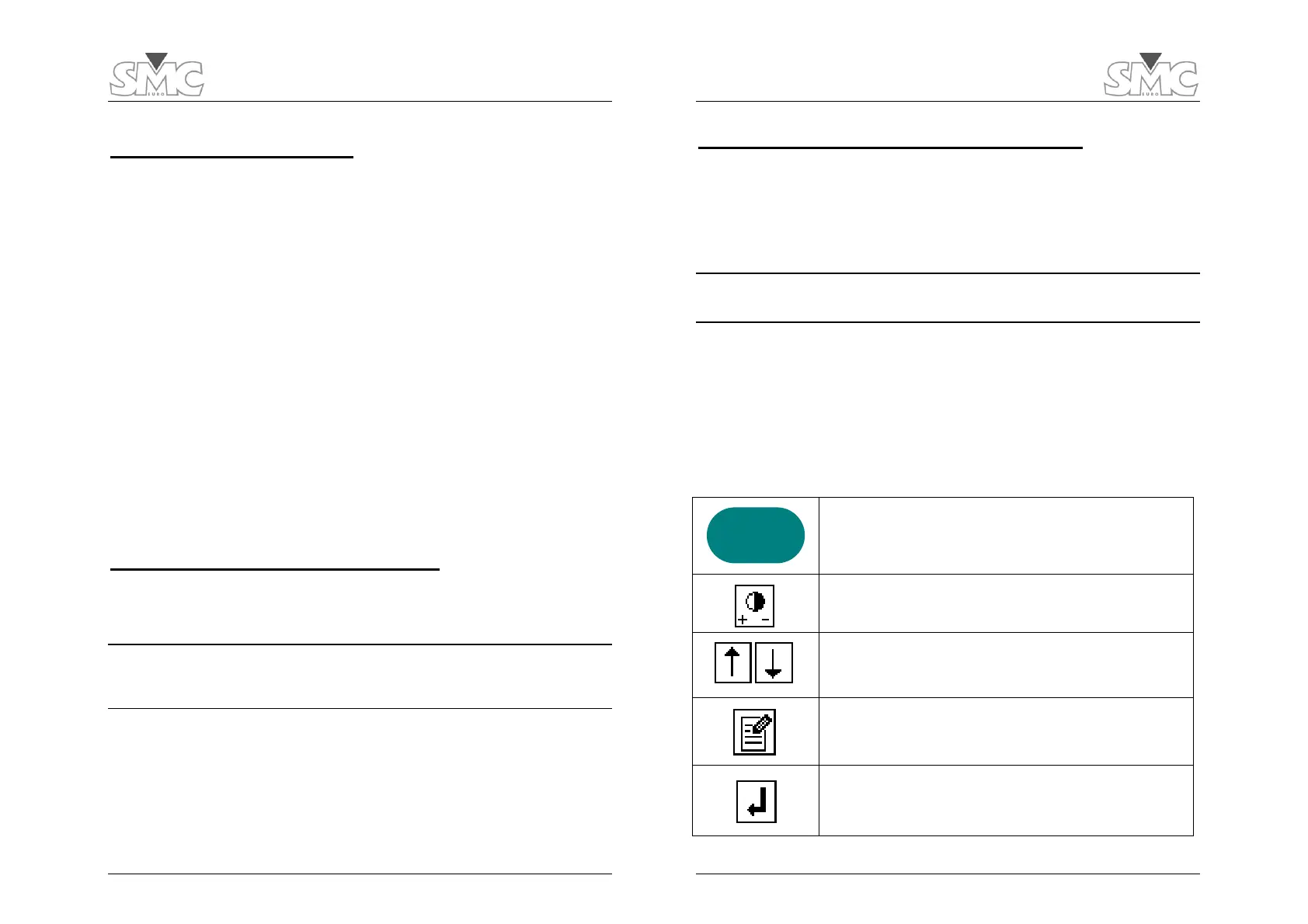
Touch Screen Buttons
All the operation of the PME-500-TR is carried out by means of the ON/OFF switch and
the touch screen buttons in the LCD panel. A description of these buttons follows.
The ON/OFF switch serves two purposes: 1) turning the unit
ON or OFF when held down for a few seconds, and 2) turning
the LCD backlight on and off with a short press.
LCD contrast adjustment. Press and hold to increase the
contrast. Release, then press and hold to decrease… and so on.
Up and Down cursor arrows allow navigation through data
fields, parameter values and menu choices.
Edit Button. Touch it to modify selected data fields or
parameter choices.
Enter Button. Touch it to confirm the setting of a parameter or
a selection from a menu.
ON / OFF
 Loading...