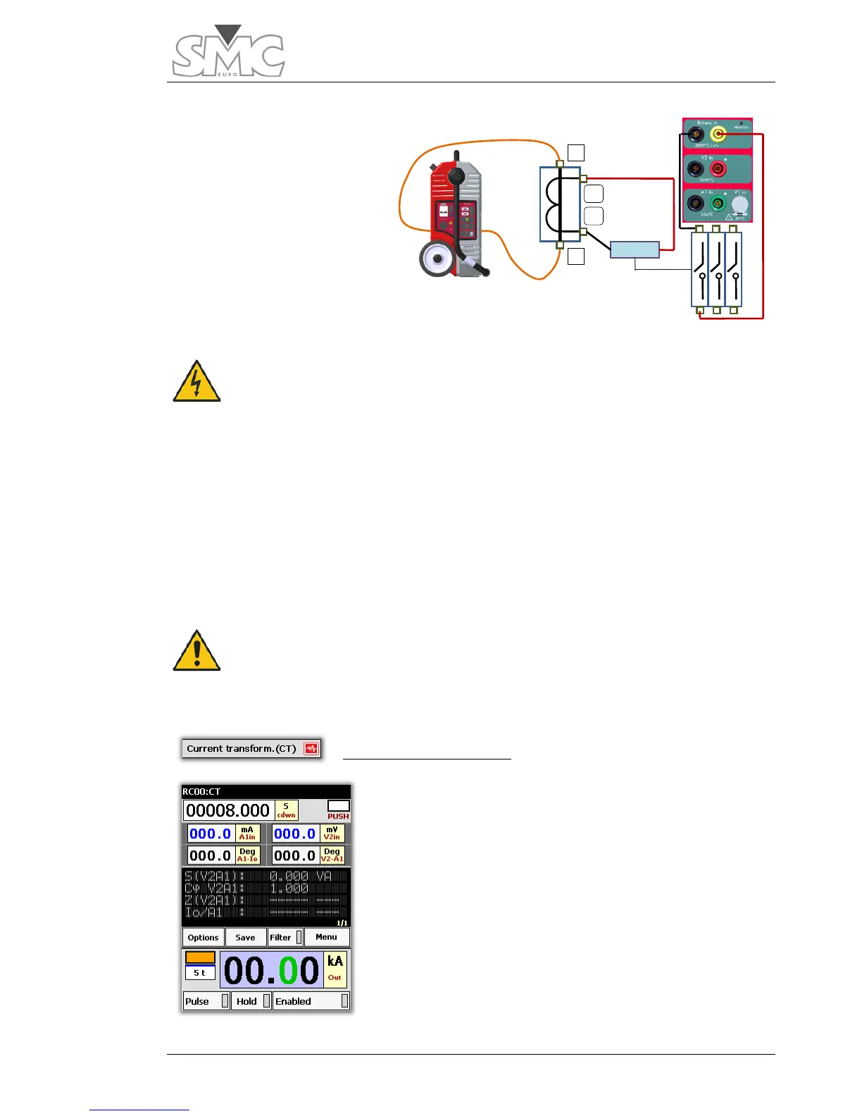
Connections:
Connect the output of the
pass-through turn to each side
of the CT Primary.
The chronometer stop signal
should be taken either from a
main contact of the circuit
breaker or from the 52a
auxiliary contact of the same
circuit breaker. Thus, the trip
time also includes the opening time of the circuit breaker and not just of the relay.
CAUTION – Make sure that the CT secondary is properly
primary with an open secondary is very risky both for the
CT and for the operator, as the CT may even explode.
Test:
Select and inject the desired current. The chronometer will start up. When the circuit
breaker trips, it will stop, indicating the trip time.
If you wish to test another point of the curve, repeat the process at another current value.
CAUTION – The trip times of an inverse time element may be
relatively high, even around several minutes. It is necessary to
ensure that the cross-section of your connection cable can support
the current for the necessary time. (see Calculator)
Current Transformer (CT)
Template designed to verify the transformation ratio in
current measurement and/or current protection
transformers (CT).
It is based on injecting current into the CT primary and
measuring the respective current in the CT secondary, thus
calculating the ratio of the transformer being tested. By
measuring the phase angle between primary and
secondary, it is possible to determine its error and its
polarity. With this same template and measuring the
voltage drop in CT secondary bushings, it is also possible
to determine the total burden of the CT in VA at the test
current, in Impedance (Z) and the power factor of the

 Loading...
