Raptor
66
Test:
Select and inject the right current value for the test, depending on the nominal secondary
current value of the CT (1 or 5A )
The chronometer will start up and it will be possible to see the test results on the meter
display. When you consider it appropriate, and by clicking on the dial, the injection will
stop, the HOLD key will be activated, blocking all the measurements and ending the test.
As nominal current is being injected, there is no heating risk for the burden or for the test
cables of the equipment.
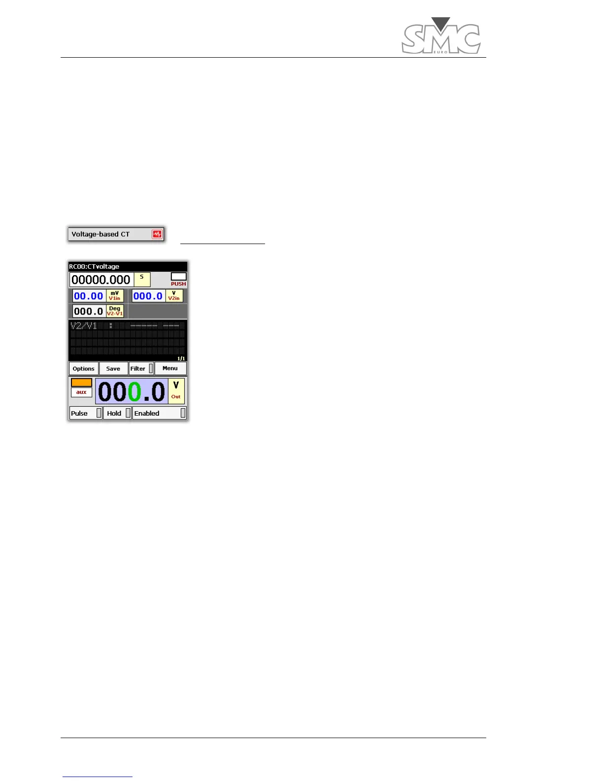
Voltage-based CT
Sometimes, there are circumstances that prevent carrying
out a ratio test on a CT properly, using current injection.
For example, a CT with very high primary current and
which, due to its location, requires very long connection
cables, thus preventing reaching sufficient current to carry
out a reliable ratio measurement.
Another typical case is that of CTs situated directly in the
high voltage bushings of power transformers, which, in
many cases, do not have an auxiliary primary connection to
allow to directly inject into the CT, so that it is impossible to
inject this current as it would have to pass through the
power windings of the transformer.
In these cases, and as an alternative, this template can be used, thus enabling us to know
the CT turn ratio and its polarity, testing it as if it were a voltage transformer.
This method obviously offers no information about the influence of the magnetic core on
the total accuracy at its precision load.
Template configuration:
The template is configured as follows:
• Generator: Auxiliary power output. Voltage Mode
• Time display: As chronometer in seconds. Stop mode: Push on dial
• V1in input voltage meter in mVolts. Auto Mode (Voltage measurement in
primary of CT).
• V2in input voltage meter in Volts. Auto Mode (voltage measurement in CT
secondary).
• Phase angle meter between voltage measured in V1in and the voltage
measured in V2in. (Primary to secondary phase angle and polarity in
degrees)

 Loading...
