• V2/V1 ratio meter which is shown as a result of the division between the two
voltages.
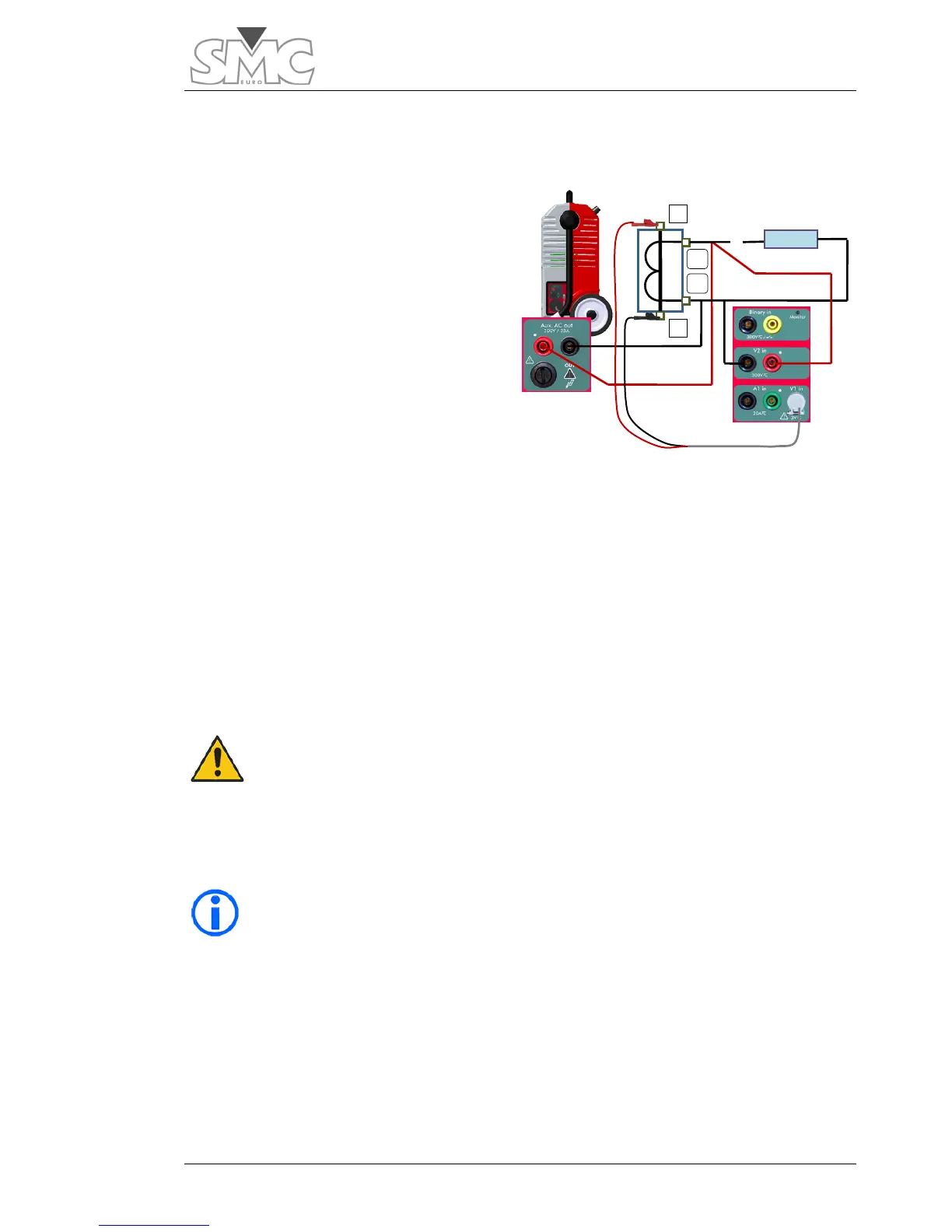
Connections:
The Auxiliary Output Power Generator is
used in voltage mode to carry out this
test, feeding the CT secondary, and the
induced voltage is measured in the
primary.
Connect as follows:
1. Connect the BLACK bushing
of the Auxiliary Output to
point S2 of the CT.
2. Connect the RED bushing of
the Auxiliary Output to bushing S1 of the CT.
3. Connect the BLACK bushing of the voltage measurement input V2 to point
S2 of the CT.
4. Connect the RED bushing of the voltage measurement input V2 to point S1
of the CT.
5. Connect point P1 of the CT to the RED tap of the voltage measurement
input V1*.
6. Connect point P2 of the CT to the BLACK tapof the voltage measurement
input V1*.
Warning – It is very important for you to make sure that the pass-
extracting the cable from the inside, if there is one, or making sure
that the turn is open, with no possibility of accidental closure.
* The level of the measurement input V1 is very low so a cable with a
special connector is used (supplied with the equipment) to shield the
measurements well from possible electromagnetic noise. In ambients
where there is loud noise, the tip of the YELLOW cable (Earth) must be
connected to the earth of the system, or at least to the BLACK tip of the
measurement cable.

 Loading...
