Raptor
34
AVAILABLE MEASUREMENTS
The Raptor system has broad measurement capacity. On the one hand, it has the
capacity to measure times, and on the other, various electrical magnitudes. This second
group has been divided into three types. The first type are measurements called Internal
Measurements, used by the system to adjust injection. The second type are ‘Hardware’
measurements, which are those obtained through specific electronic circuits included in
the Raptor-MS case. The third type, ‘Calculated’ measurements, is obtained through
calculations based on the Internal and Hardware measurements.
Internal measurements
These measurements are related directly to the injected magnitude, and they are not
directly visible, given that they are those that the processor uses to adjust the injected
magnitude selected by you.
The main current meter is a Rogowsky type of sensor included in the Raptor-MS case,
which surrounds the hole where the pass-through turns are inserted. Due to the
characteristics of this sensor, it measures the total current flow passing through the
system. This is why, when using injection by pass-through turns, you must be sure that the
number of turns specified on the console is the actual number. Even though this type of
measurement is very precise, to improve the measurement the system has 2 ranges,
which you must select. You can access this configuration as described in step 2 of the
chapter, “Making the first current injection”.
When you use injection through the auxiliary Voltage or Current outputs located on the
expansion panel of the Raptor-MS unit, there is also an internal measurement of these
magnitudes. This is a low-accuracy measurement, of around 5%. If you require greater
precision, it is advisable to simultaneously use the external meters to compare the real
injected value.
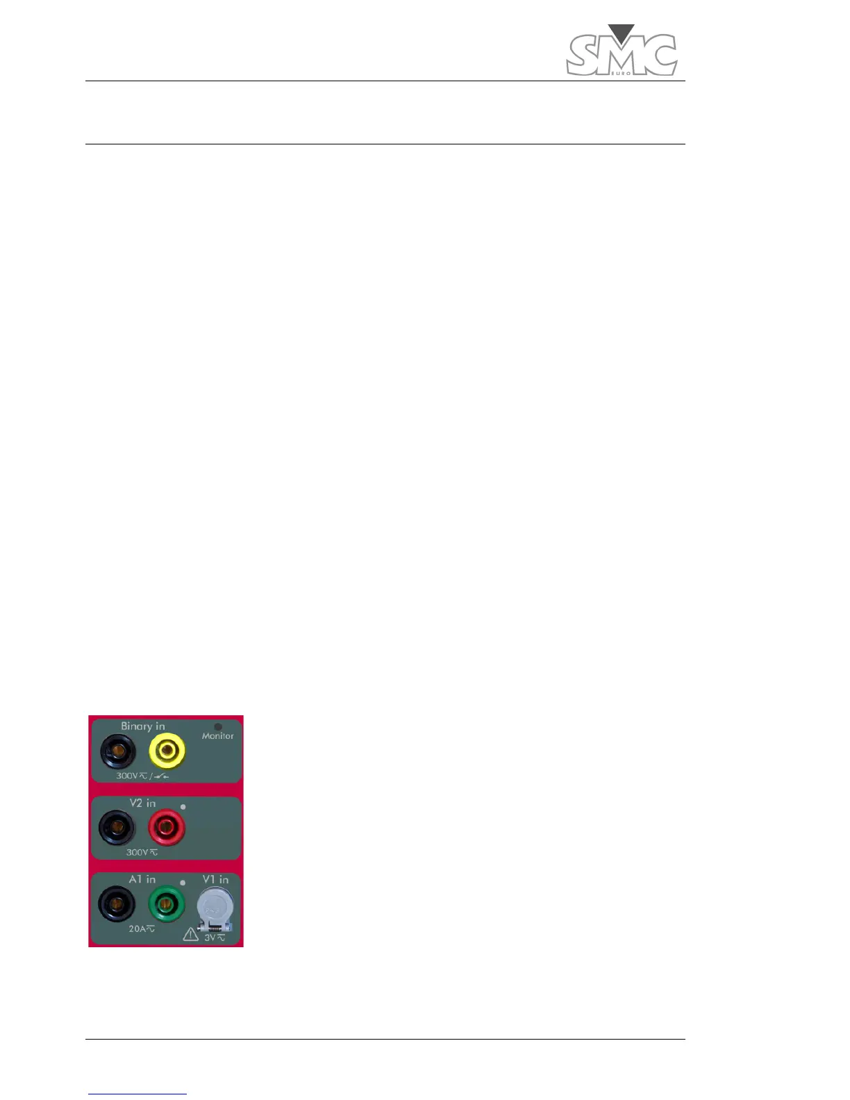
Hardware measurements
In addition to the binary input related to the chronometer, the
main panel of the Raptor-MS unit has three measurement
inputs, two for voltage and one for current.
These inputs are connected to level sensors on one side and
are taken by pairs (including the internal measurements) to
phase sensors.
The
A1in
current input shares circuitry with the
V1in
low-voltage
input, and they both cannot be used as the same time. An
orange zone on the selector indicates which one is active (even
though it may not be selected for display).
The ‘Hardware’ measurements are obtained based on these
sensors.

 Loading...
