Users Guide
59
equipment, follow the steps below:
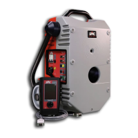
1. Connect the GREY coloured side of the RAPTOR to the input indicated as
“Incoming current” of the Sensor.
2. Connect the RED coloured side of the RAPTOR to the input indicated as
“Outgoing current” of the Sensor.
3. Connect the RED bushing of measurement input V1* to the secondary
output of the Sensor, indicated as V.
4. Connect the BLACK bushing of measurement input V1* to the secondary
output of the Sensor, indicated as 0.
*The level of the measurement input V1 is very low so a cable with a special connector is
used (supplied with the equipment) to shield the measurements well from possible
electromagnetic noise. In ambients where there is loud noise, the tip of the YELLOW cable
(Earth) must be connected to the earth of the system, or at least to the BLACK tip of the
measurement cable.
With this connection, the phase angle between primary and secondary must be zero or
very close to this value, indicating correct polarity. If the device tested is a direct Rogowski
sensor, not electronically compensated, the standard correct value is 90º.
Test:
Select and inject the desired current. The timer will start up. When the countdown reaches
zero, the injection will stop and the HOLD key will be activated, blocking all the
measurements and ending the test.
If you wish to test another point of the Sensor, repeat the process at another current
value.
When a Sensor is tested, it is usually advisable to test the ratio error and phase angle at
different primary currents to verify linearity.
If the measurements are seen to be unstable, and their values are continuously changing,
use the FILTER option to see the most stable values.
If you find the default measurement time on the Template (8 s) short
and you wish to increase it, do so, but bear in mind the cable cross-
section used (the cable may overheat).

 Loading...