Users Guide
61
• V1in input secondary voltage meter in Volts. Auto Mode (voltage drop
between the points selected).
• Phase angle meter between voltage V1in and primary current Io.
• Power factor meter (cos phi) between V1 and Io.
• Impedance (Z) meter between the selected points.
• Real part (R) meter between the selected points.
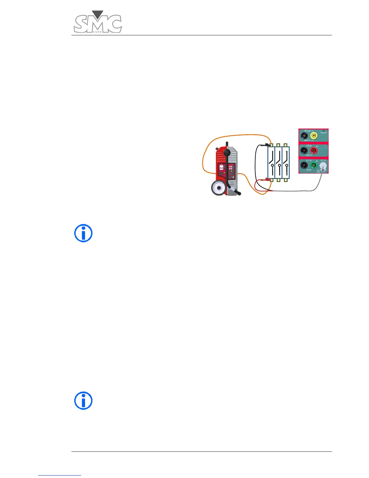
Connections:
Connect the output of the pass-
through turn to each side of the point
selected to be measured.
Connect the tips of the test cable of
input V1*, always between the
previous current ones, never outside.
The polarity does not matter.
* The level of the measurement input V1 is very low so a cable with a
special connector is used (supplied with the equipment) to shield the
measurements well from possible electromagnetic noise. In ambients
where there is loud noise, the tip of the YELLOW cable (Earth) must be
connected to the earth of the system, or at least to the BLACK tip of the
measurement cable.
Test:
Select and inject an adequate current value for the test*.
*In general, talking about contact resistances of circuit breakers and sectionalizers or
busbar connection points, currents of around 500 A should be more than safe. In any
case, and whenever possible, try to inject the maximum current that can be obtained
from the system, without overloading the capacity of the point tested. The minimum
current to carry out this test must be over 100 A to be able to obtain reliable results.
The timer will start up. When the countdown reaches zero, the injection will stop and the
HOLD key will be activated, blocking all the measurements and ending the test.
If you find the default measurement time on the Template (8 s) short
and you wish to increase it, do so, but bear in mind the cable cross-
section used (the cable may overheat).

 Loading...
