Template configuration:
The template is configured as follows:
• Generator: Auxiliary power output. Voltage Mode
• Time display: As chronometer in seconds. Stop mode: Push on dial
• V1in input voltage meter in mVolts. Auto Mode (Voltage measurement in
secondary of VT).
• V2in input voltage meter in Volts. Auto Mode (voltage measurement in
primary of VT).
• Phase angle meter between voltage measured in V1in and the voltage
measured in V2in. (Secondary to primary phase angle and polarity in
degrees)
• V2/V1 ratio meter which is shown as a result of the division between the two
voltages.
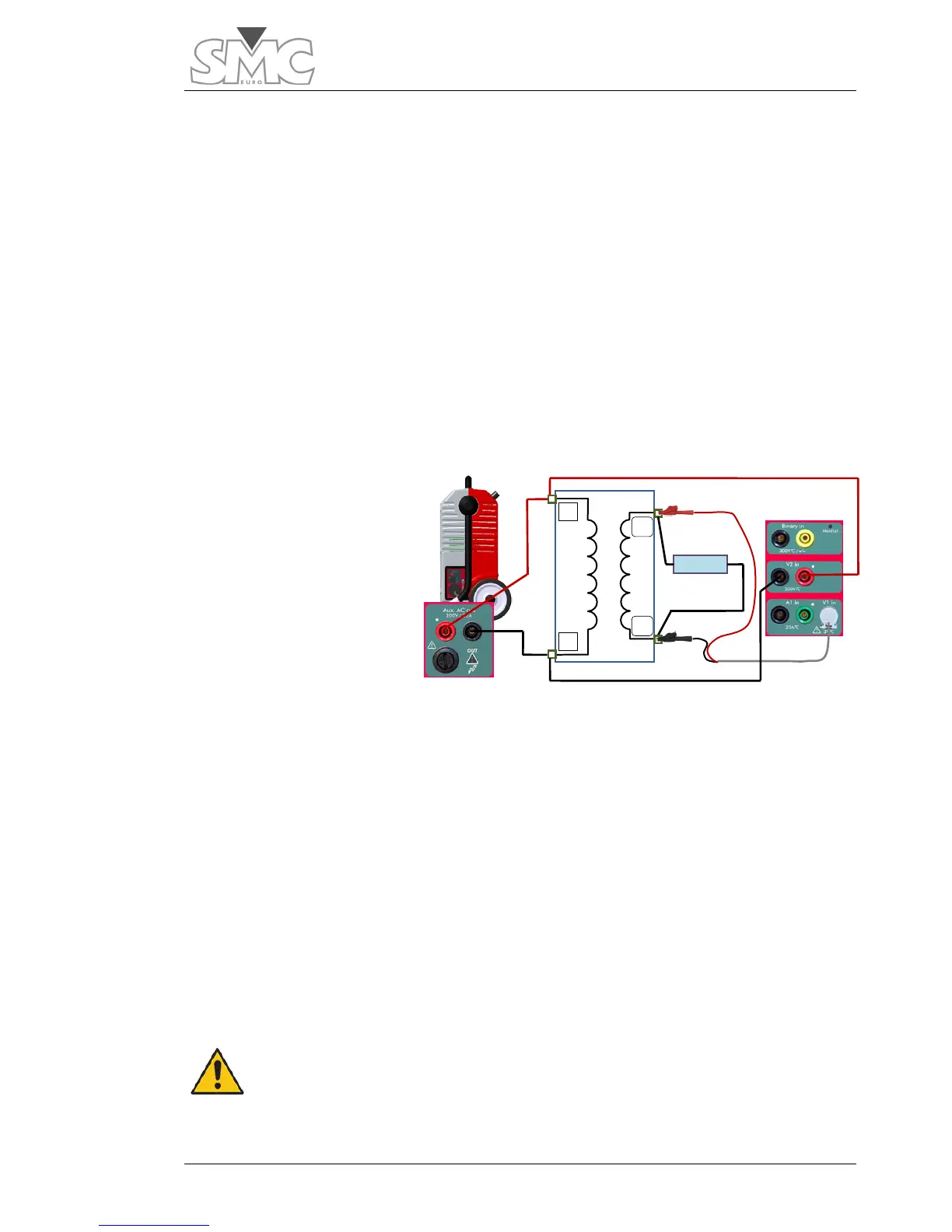
Connections:
The Auxiliary Output Power
Generator is used in
voltage mode to carry out
this test, feeding the VT
primary, and the induced
voltage is measured in the
secondary.
Connect as follows:
1. Connect the RED bushing of the Auxiliary Output to point P1 of the VT.
2. Connect the BLACK bushing of the Auxiliary Output to bushing P2 of the VT.
3. Connect the RED bushing of the voltage measurement input V2 to point P1
of the VT.
4. Connect the BLACK bushing of the voltage measurement input V2 to point
P2 of the VT.
5. Connect point S1 of the VT to the RED bushing of the voltage measurement
input V1*.
6. Connect point S2 of the VT to the BLACK bushing of the voltage
measurement input V1*.
Warning – It is very important for you to make sure that the pass-
extracting the cable from the inside, if there is one, or making sure
that the turn is open, with no possibility of accidental closure.

 Loading...
