8
Introduction Data and Power Connections
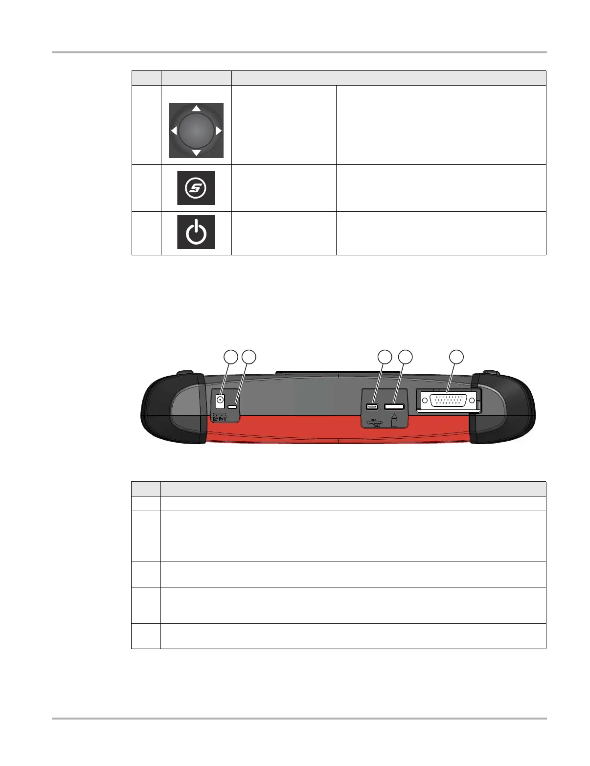
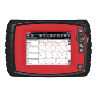
2.2 Data and Power Connections
Connectors and jacks for the scope multimeter, data communication cables and the AC power
supply are located on the top of the Diagnostic Tool.
Figure 2-2 Top view
3
Directional - Thumb
pad rocker type buttons
Buttons move the cursor or highlight in their
respective direction:
• Up (b)
• Down (d)
• Left (e)
• Right (c)
4
S (Shortcut) - Push type
button
Programmable function button that can provide a
shortcut for performing a variety of routine tasks.
Refer to Configure Shortcut Button‚ on page 57 for
additional information.
5
Power (On/Off) - Push
type button
Turns the Diagnostic Tool on and off. Also, press
and hold for 5 seconds for emergency shutdown
Item Button Description
Item Description
1 DC Power Supply Jack - AC power supply connection
2
Battery Status Indicator LED
• Green - battery is fully charged
• Red - battery is charging
• Amber - indicates there is a battery issue (correct before operating)
3
Mini USB Jack - USB cable connection used to connect the Diagnostic Tool to a personal
computer
4
Micro secure digital (uSD) Card - contains operating system programming. IMPORTANT The
uSD card must be installed for the Diagnostic Tool to operate. Do not remove the uSD card
while the Diagnostic Tool is powered on.
5
Data Cable Connector - Data cable connection used to connect the Diagnostic Tool to a vehicle
data link connector