19
Basic Operation and Navigation Data Cable Connection
3.4 Data Cable Connection
Connection of the data cable to the Diagnostic Tool and vehicle DLC is required for Scanner and
OBD-II/EOBD testing.
Depending on the vehicle, the supplied DA-4 data cable may be used alone or may require
optional adapters.
• All OBD-II/EOBD compliant vehicles - Use the supplied DA-4 data cable. The 26-pin end of
the cable attaches to the data cable connector on the top of the Diagnostic Tool. The16-pin
end connects to the vehicle DLC. The cable connectors are secured with captive screws.
• All non-OBD-II/EOBD (OBD-I) compliant vehicles - Use the supplied DA-4 data cable with
the optional DA-5 adapter and a manufacturer specific adapter. The 26-pin end of the cable
attaches to the data cable connector on the top of the Diagnostic Tool. The16-pin end
connects to the DA-5 adapter, the DA-5 adapter connects to the manufacturer specific adapter
and then connects to the vehicle DLC. The cable connectors are secured with captive screws.
On-screen cable and adapter connection instructions are provided while using the Scanner and
OBD-II/EOBD functions. The instructions may also include the location of the vehicle DLC
(Figure 3-3). If required, additional connection information can be found in the appropriate vehicle
communication software manual for the vehicle. Vehicle communication software manuals are
available online, see the website information at the front of this manual
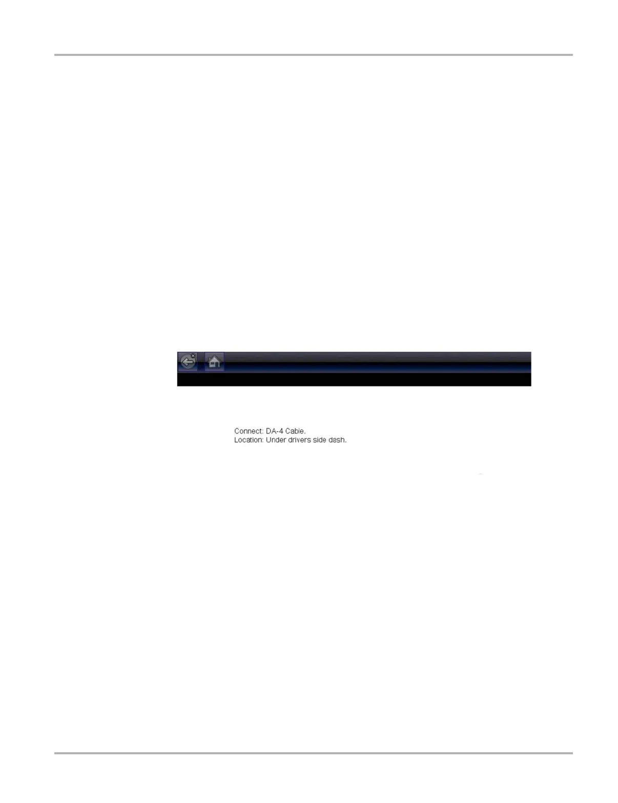
Figure 3-3 Vehicle connection data cable message
For data cable vehicle power connection information, see "Vehicle Power‚" on page 10.
z To connect the data cable to the vehicle:
1. Follow the on-screen instructions for connecting to the vehicle (Figure 3-3).
2. Select Continue once the data cable is connected.
The Diagnostic Tool establishes communication then displays a list of available tests. If the
Diagnostic Tool is unable to establish a communications link, a “no communications” message
displays.
3. Select from the available tests to open a submenu of test options.