Do you have a question about the Snap-On SOLUS Ultra and is the answer not in the manual?
Details about Snap-on and other trademarks used in the publication.
Copyright details for the manual's content.
States limitations on warranty and liability for the manual's content.
Details governing the use of the diagnostic tool's software.
Information on patents protecting Snap-on products.
Notes on manual applicability, versions, and updates.
Contact methods for technical support via phone or email.
URLs for Snap-on diagnostics and technical documentation.
Information on accessing free training videos for diagnostic tool operation.
Details on where to find diagnostic quick tips videos online.
Emphasizes reading all safety messages and specifies operating conditions.
Defines hazard signal words and text conventions in safety messages.
Refers to a separate manual for a complete list of safety messages.
Overview of manual structure, terminology, and formatting.
Explains bold text, notes, important messages, and hyperlinks.
Describes how procedures are indicated and formatted in the manual.
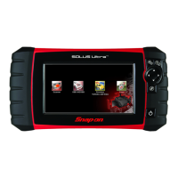
Introduces the diagnostic tool's front panel control buttons and their functions.
Details the location and function of various connectors and jacks.
Describes the built-in stand and battery cover.
Lists the sources from which the diagnostic tool can receive power.
Details on internal battery, AC supply, and vehicle power sources.
Lists detailed technical specifications of the diagnostic tool.
Procedures for powering the tool on, off, and emergency shutdown.
Introduces navigation and the home screen layout.
Explains the elements and information displayed in the title bar.
Describes the function of each icon on the home screen.
Describes common control icons used in toolbars across functions.
Explains the function and use of the screen scroll bar.
Explains system and communication error messages.
Details how to connect the data cable to the tool and vehicle.
Describes the screen layout and toolbar icons for Scanner and OBD-II/EOBD.
Details the screen layout for Scanner and OBD-II/EOBD functions.
Lists and describes control icons specific to the Scanner function.
Guide to starting and using the demonstration program.
Overview of scanner operation and vehicle identification.
Procedure for connecting the data cable for scanner testing.
How to select vehicle systems and tests within the Scanner.
Options for viewing diagnostic trouble codes.
How DTC results are displayed and interpreted.
How to save and review diagnostic trouble codes.
Customizing data lists and changing screen display views.
How to lock parameters to keep them in place on the display.
How to set trigger levels for automatic data capture.
Procedures for saving and reviewing data files.
Saving screen snapshots and pausing data for review.
Navigating data during pause and resuming.
How to access vehicle-specific subsystem tests.
Performing generic OBD-II tests and using the troubleshooter.
Procedures for safely exiting the scanner function.
Overview of basic operations for OBD-II/EOBD.
Screen layout, data cable connection, and file handling for OBD-II/EOBD.
Lists options available in the OBD-II/EOBD menu.
Checking DTCs, readiness monitors, and global codes.
Details on codes, pending codes, clearing data, and readiness monitors.
Checking MIL status and displaying current emission-related data.
Displaying freeze frame data, trouble codes, and clearing emissions data.
Submenu for parameters, test results, and DTC conditions.
Controlling onboard systems, reading vehicle ID, and performance tracking.
Displays permanent DTCs and vehicle connector locations.
Manually select communication protocols if auto-detect fails.
Lists options for accessing vehicle history and saved data.
Stores and displays the last 25 vehicles tested.
Opens a list of data movies and screen images stored in memory.
Permanently erases saved files from diagnostic tool memory.
Lists options for configuring diagnostic tool settings.
Configure PC connection, shortcut functions, view system info, and adjust settings.
Adjusting system display settings and screen brightness.
Options for screen theme and toolbar contrast.
Adjusting font, backlight timer, and touch screen calibration.
Setting the local time zone and adjusting the real-time clock.
Configuring DST and the time display format.
Selecting date format and configuring scanner graph scales.
Choosing between US customary or metric units of measure.
Tasks for keeping the diagnostic tool in top shape.
Battery service, safety guidelines, and replacement procedures.
Guidelines for disposing of lithium-ion battery packs.
Steps to connect the diagnostic tool to a PC for SSC.
Layout of the main screen for ShopStream Connect software.
Viewing and configuring data files recorded by the diagnostic tool.
Viewing and printing image files (screenshots) saved on the tool.
Steps to print code scan reports using ShopStream Connect.
Information on software upgrades and service releases.
Requirements for accepting the End User License Agreement.
Introduction to the SureTrack online community and its features.
Links to key topics and FAQ for SureTrack.
Where to find the SureTrack authorization code on sales receipts.
Procedure for new users to create a SureTrack account.
Steps to log into an active SureTrack account.
Steps to log in with a new code for an active account.
Steps to log in with a new code for an expired account.
Details the features of the SureTrack system.
Overview of the SureTrack Home page within ShopKey Pro.
Explains the results index page and its content.
Displays applicable repair information on the SureTrack results page.
Opens ProView for graphical display of code-to-component relationships.