UPS/NTA GB/DELMP_EXPC1C3C6_B 29
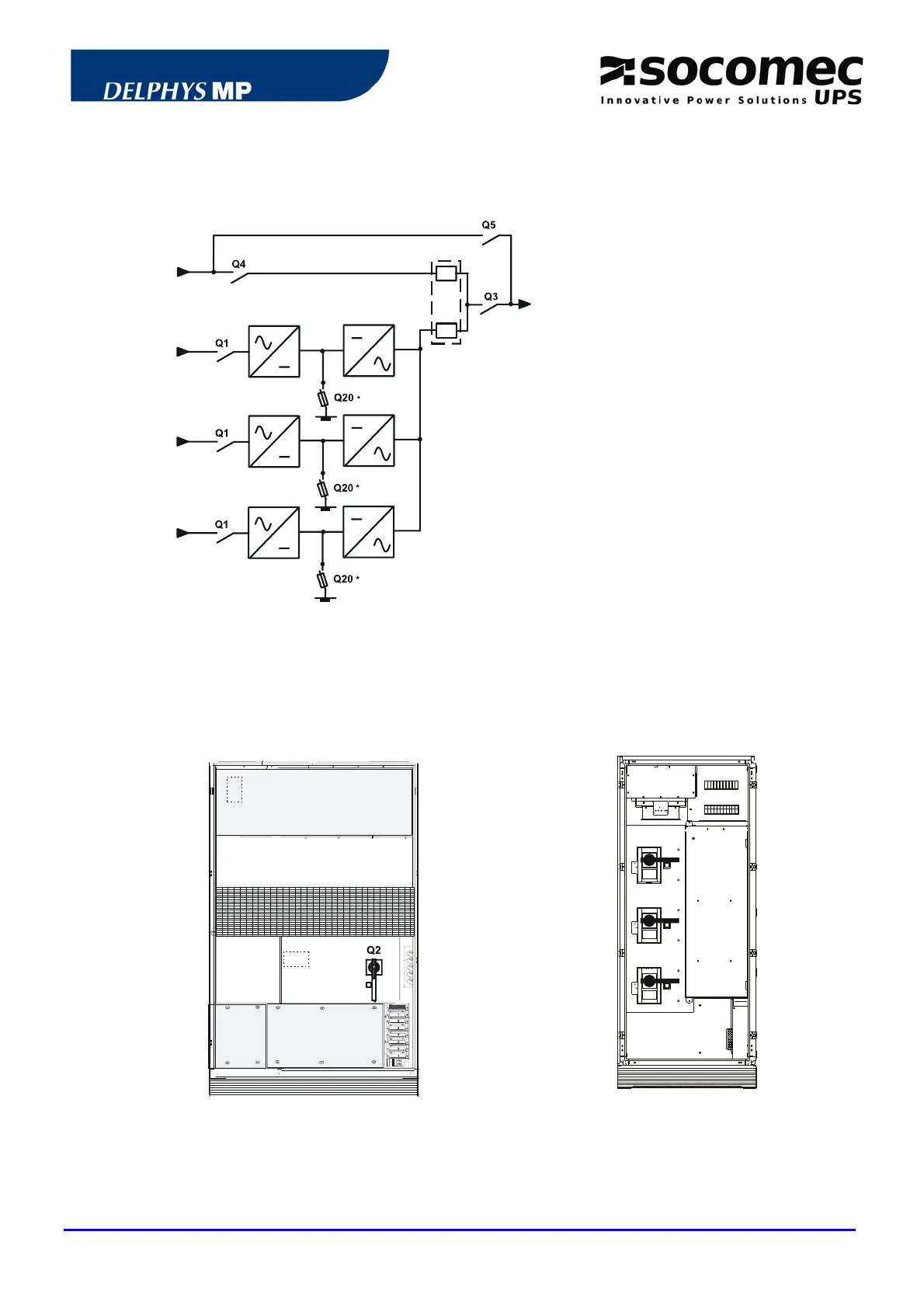
4.1 STANDARD BASIC SCHEME
Central bypass systems can include up to six modules in parallel.
MBP
ABP
BP
50
X40
X10
REC INV
X20
X20
X20
X10
REC INV
X10
REC INV
X10: rectifier input
X40: bypass input
X50: to the load
REC: rectifier
INV: inverter
BAT: battery
BP: bypass facility
ABP: automatic bypass
MBP: maintenance bypass
* other protection upon request
NOTE: in any case, see the technical details of the drawing.
4.2 LAYOUT OF SWITCHES
UPS UNIT BYPASS CABINET
Q4
Q5
Q3
Q2: Unit output switch
Q20: Battery protection in the battery
enclosure or cabinet
Q1: Input rectifier switch (optional)
Q4: Input automatic bypass switch
Q3: Output switch to the load
Q5: Maintenance bypass switch
 Loading...