54 EN
MASTERYS GP4 60-160 kVA - Ref.: IOMMASGPXX07-EN 05
11.1 ADC+SL card
The ADC+SL (Advanced Dry Contact + Serial Link) is a slot optional board that provides:
• 4 relays for external device activation (can be set as normally closed or normally open).
• 3 free inputs to report external contacts to UPS.
• 1 connector for external battery temperature sensor (optional).
• RS485 insulated serial link providing MODBUS RTU protocol.
• 2 LEDs indicating board status.
The board is plug&play: the UPS is able to recognise its presence and configuration (up to 4 standard operating
modes can be selected by the display) and manages the ADC+SL outputs and the inputs accordingly. It is possible
to create a custom operation mode through after sales service.
IN1-
IN1+
IN2+
IN2-
-
+
IN1-
IN1+
IN3+
IN3-
C2
NO2
NO4
C4
C1
NO1
C3
NO3
NC1
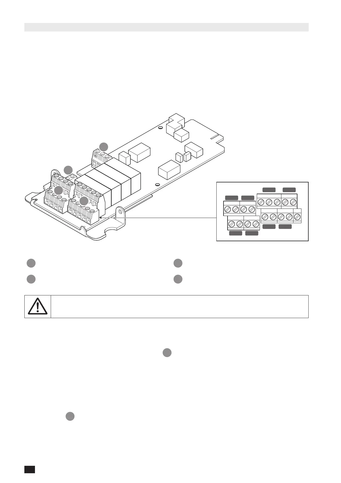
A
C
D
B
IN1- IN1+ IN2- IN2+
IN1- IN1+ IN3- IN3+
C1 NO1 NC1 C3 NO3
C2 NO2 C4 NO4
IN1 IN3
IN1 IN2
OUT1 OUT3
OUT2 OUT4
KEY
A 3 free inputs to link external contacts to UPS. C 1 connector for external temperature sensor.
B 4 relays for external device activation. D RS485 insulated serial link.
NOTE!
If the board is removed while operating, an alarm is flagged on the control panel.
Perform an “Alarm reset” control to cancel it.
Input
• Free voltage loop.
• INx+ has to be connected to INx- to close the loop on
A
connector.
• Inputs must be isolated with basic insulation from a primary circuit up to 277 V.
• IN1 is duplicated, giving the possibility to link the UPS POWER OFF signal to other equipment, for example.
Relay outputs
• Contact voltage guaranteed at 277 V (AC) / 25 V (DC) – 4 A (for higher voltage, please contact the manufacturer).
• Relay 1 gives the possibility of choosing between normally closed (NC1) or normally open (NO1) position. Relays 2,
3 and 4 only have normally open position (NOx).
• On connector
B
, Cx means common, NOx means normally open position.