Step 4 After crimping is complete, insert the crystal head into the RJ45 port of the Auxiliary
Power Module.
Step 5 After the wiring is completed, gently tug on the cable to ensure that there is a margin, the
corresponding PG header must lock the cable, and tie up the communication network cable according
to the alignment path.
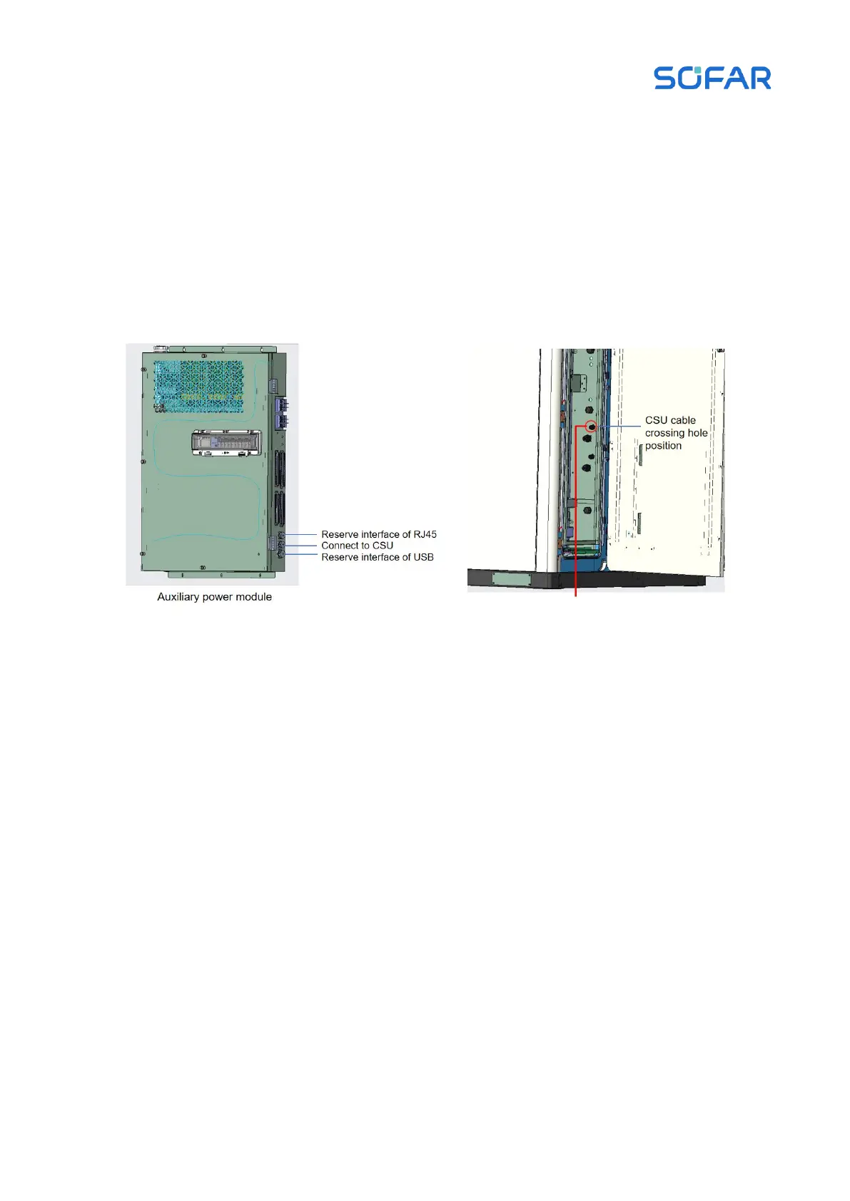
Figure 5.28 Schematic diagram of CMU communication network cable connection
CSU communication network cable
If the CSU is integrated in energy storage cabinet, perform this step. Then the external network
cable is going from the host computer to the CSU of the energy storage cabinet, the communication
network cable wiring position is at the RJ45 port of the CSU, and the communication network cable
wiring of the CSU is shown in the following figure.