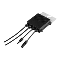
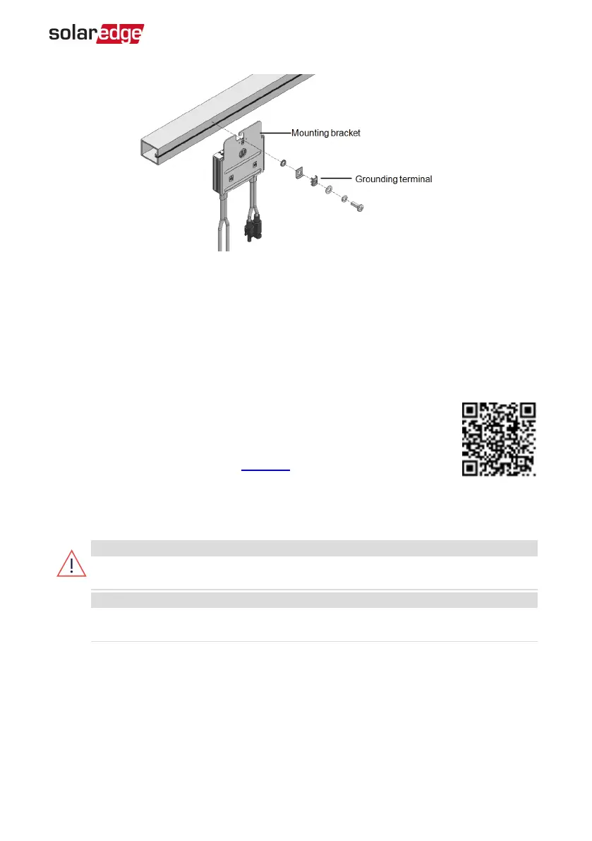
Figure 8: Power optimizer grounding terminal
5. Verify that each power optimizer is securely attached to the module support
structure.
6. Record power optimizer serial numbers and locations, as described in
Reporting and
Monitoring Installation Data
on page 55.
Step 3: Connecting Power Optimizers in Strings
You can construct parallel strings of unequal length, that is, the number
of power optimizers in each string does not have to be the same. The
minimum and maximum string lengths are specified in the power
optimizer datasheets. Refer to the Designer for string length verification.
1. Connect the Minus (-) output connector of the string’s first power optimizer to the
Plus (+) output connector of the string’s second power optimizer.
2. Connect the rest of the power optimizers in the string in the same manner.
WARNING!
If using a dual-input power optimizer and some inputs are not used, seal the
unused input connectors with the supplied pair of seals.
AVERTISSEMENT!
Si un optimiseur à double entrées est utilisé et que certaines entrées ne sont pas
connectées, fermez ces entrées avec la paire de couvercles fournie.
Chapter 2: Installing the Power Optimizers 27
EV Charging Single Phase Inverter Guide MAN-01-00588-1.1