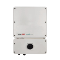
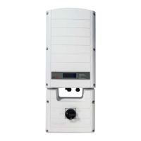
Connection Unit with Safety Switch Interface
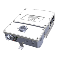
EV Charger cable connector: Used for connecting the EVcharger cable to the
inverter
EV Charger LED indicator: Three LEDs indicate the EV Charger statuses.
Figure 11: LEDs
The following table lists the LED indications when the EV Charger Cable is connected to
the inverter and activated (refer to the EV Charger Cable Installation Guide supplied with
the EV Charger Cable):
Color Description
All LEDs OFF - No AC power
Red ON - Error
Blue
ON - the EVCharger is communicating with the inverter
OFF - the EVCharger is not communicating with the inverter
Green
ON - Charging
Blinking
(1)
- the EVCharger is plugged in but not charging
Flickering
(2)
- the EVCharger is ready to charge but not plugged in
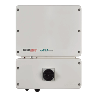
ACoutput / input : For connection of the AC grid
DC input : For connection of the PV installation
Communication gland: For connection of inverter communication options. Refer
to
Setting Up Communication to the Monitoring Platform
on page 58 for more
information.
(1)
Lights ON for 1000mS and OFF for 1000mS
(2)
Lights ON for 100mS and OFF for 5000mS
Chapter 3: Installing the Inverter 31
EV Charging Single Phase Inverter Guide MAN-01-00588-1.1