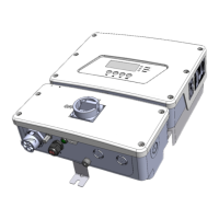
Figure 17: Hanging the inverter on the brackets
6.
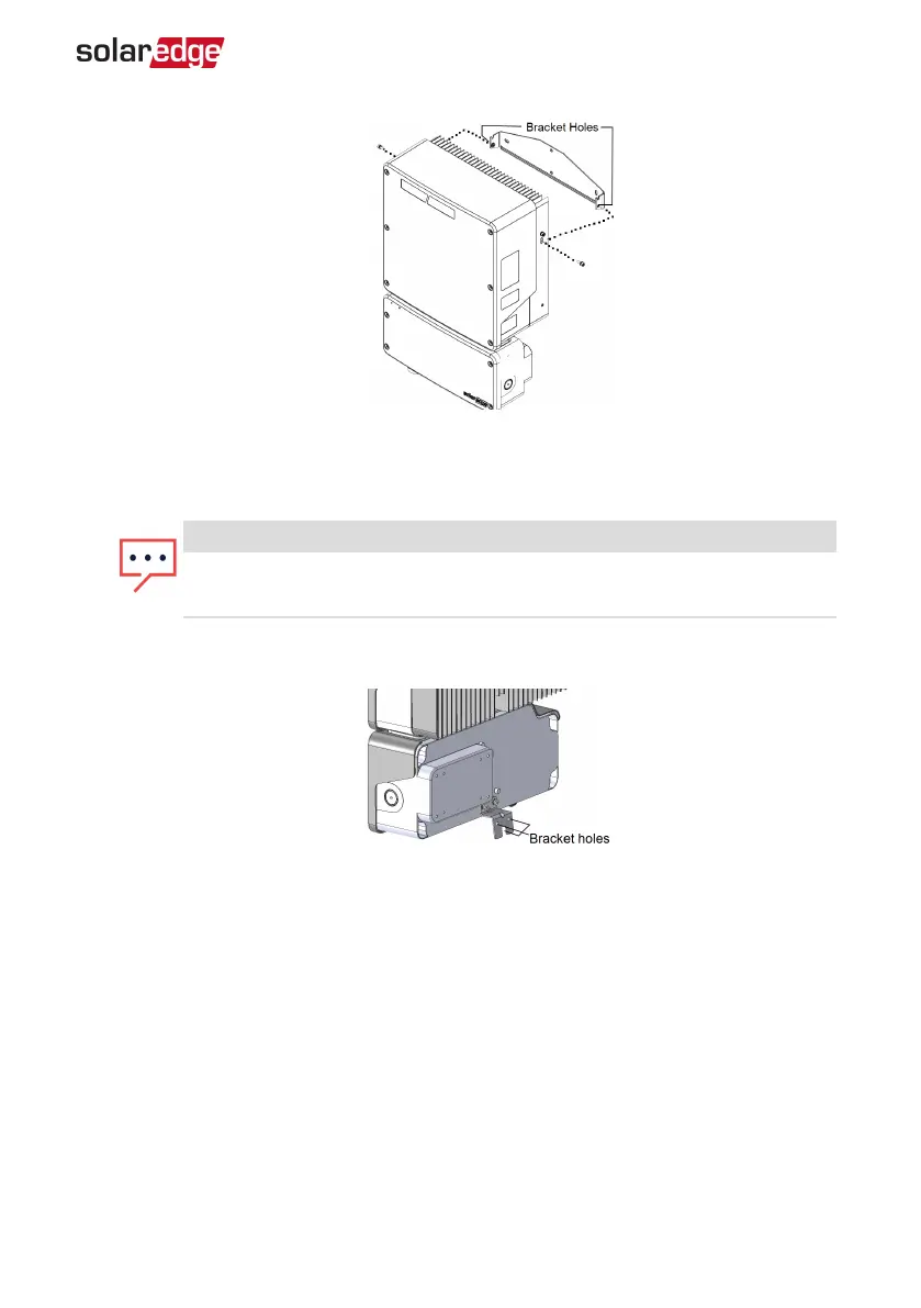
Optionally, secure the Connection Unit with Safety Switch bracket to the wall/pole,
using 3 screws:
NOTE
In case of inverter replacement with the Connection Unit with Safety Switch
still mounted, it is recommended to use all 3 holes.
a.
Mark the location of the bracket screw for the Connection Unit with Safety
Switch, and optionally the two additional bracket holes.
Figure 18: Connection Unit with Safety Switch bracket
b. Remove the inverter from the wall/ pole.
c. Drill the hole for the Connection Unit with Safety Switch bracket.
d. Hang the inverter on the mounted brackets.
e. Fasten the Connection Unit with Safety Switch bracket using a standard bolt.
7. Insert the screws at the top of the inverter brackets and fasten the brackets together.
8. Verify that all the brackets are firmly attached to the mounting surface.
Chapter 3: Installing the Inverter 37
EV Charging Single Phase Inverter Guide MAN-01-00588-1.1