3. Remove the plastic seal from one of the large openings.
4. Remove the rubber fitting from the gland and insert the CAT5/6 cable through the
gland and through the gland opening in the inverter.
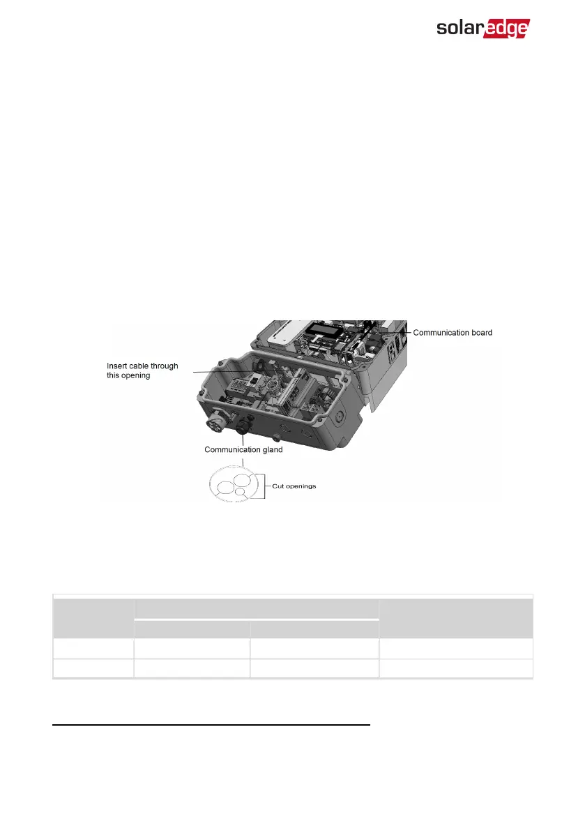
5. Insert the cable through the opening in the Connection Unit with Safety Switch
towards the communication board.
6.
Push the cable into the cut opening of the rubber fitting.
Figure 24: Communication glands and rubber fitting
CAT5/6 standard cables have eight wires (four twisted pairs), as shown in the diagram
below. Wire colors may differ from one cable to another. You can use either wiring
standard, as long as both sides of the cable have the same pin-out and color-coding.
RJ45 Pin #
Wire Color
(1)
10Base-T Signal
100Base-TX Signal
T568B T568A
1 White/Orange White/Green Transmit+
2 Orange Green Transmit-
(1)
The inverter connection does not support RX/TX polarity change. Supporting crossover Ethernet cables
depends on the switch capabilities.
EV Charging Single Phase Inverter Guide MAN-01-00588-1.1
64 Creating an Ethernet (LAN) Connection