RJ45 Pin #
Wire Color
(1)
10Base-T Signal
100Base-TX Signal
T568B T568A
3 White/Green White/Orange Receive+
4 Blue Blue Reserved
5 White/Blue White/Blue Reserved
6 Green Orange Received-
7 White/Brown White/Brown Reserved
8 Brown Brown Reserved
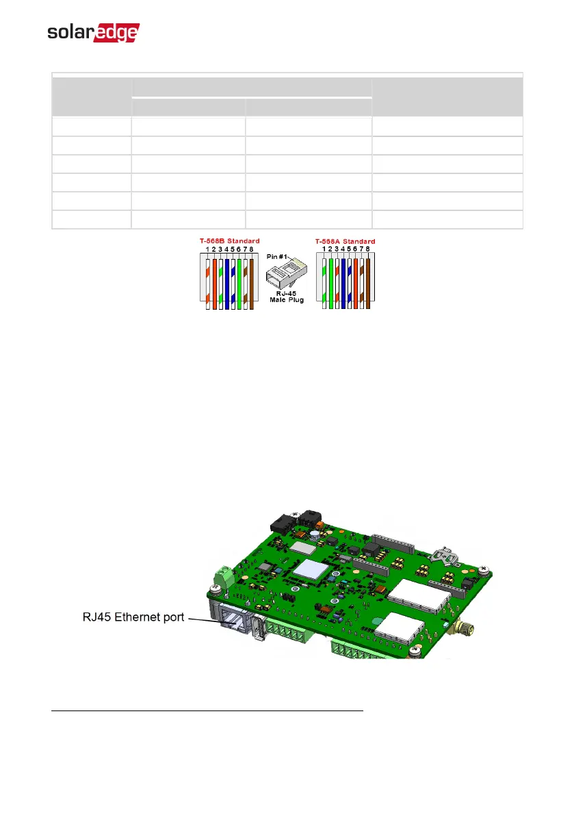
Figure 25: Standard cable wiring
7. Use a pre-crimped cable to connect via gland #1 to the RJ45 plug on the inverter's
communication board or, if using a spool of cable, connect as follows:
a. Insert the cable through the gland.
b. Remove the cable’s external insulation using a crimping tool or cable cutter and
expose eight wires.
c. Insert the eight wires into an RJ45 connector, as described in
Figure 25
d. Use a crimping tool to crimp the connector.
e. Connect the Ethernet connector to the RJ45 port on the communication board.
Figure 26: The RJ45 Ethernet connection
(1)
The inverter connection does not support RX/TX polarity change. Supporting crossover Ethernet cables
depends on the switch capabilities.
Chapter 5: Setting Up Communication to the Monitoring Platform 65
EV Charging Single Phase Inverter Guide MAN-01-00588-1.1