5. Disconnect the DC wires from the inverter and the ACwires from the Connection
Unit with Safety Switch.
6.
Disconnect the wires connected between the inverter and the Connection Unit with
Safety Switch:
Antenna cable from the communication board
RS485 and/or Ethernet connection from the communication board
Grounding cable
7.
Open the Connection Unit with Safety Switch bracket screws.
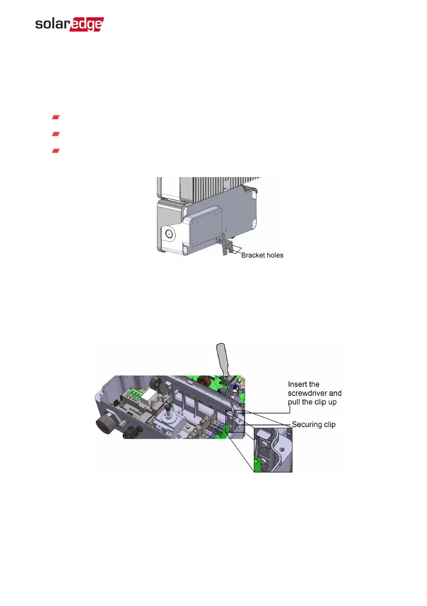
Figure 32: Connection Unit with Safety Switch bracket
8.
Disconnect the Connection Unit with Safety Switch from the inverter by opening the
two clips securing the Connection Unit with Safety Switch to the inverter: Carefully
place a screwdriver between the clip and the enclosure and pull the clip.
Figure 33: Disconnecting the Connection Unit with Safety Switch from the inverter
9. Detach the Connection Unit with Safety Switch from the inverter.
10. Place the new Connection Unit with Safety Switch and secure it to the inverter using
the clips.
Appendix A: Replacing and Adding System Components 81
EV Charging Single Phase Inverter Guide MAN-01-00588-1.1