Synergy Manager External Cable Interface
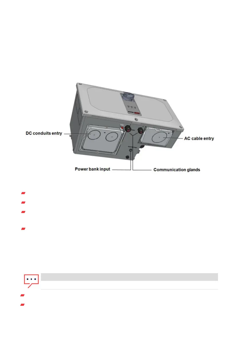
The conduit entries, at the bottom side of the Synergy Manager, interfaces the inverter
to the grid and PV arrays. The communication glands, support communication cables
connecting the inverter to the SolarEdge Monitoring platform and external power bank
used for setting up the inverter in sites with no available grid power.
Figure 13: Synergy Manager - bottom view
AC Conduits Entry: drill guides for conduits running AC cable from the grid
DC Conduits Entries: drill guides for conduits running DC cables from the PV arrays
Power Bank Input: power bank connection enables inverter pre-commissioning
when AC power is not connected
Communication Glands: two communication glands for connecting
communication and antenna cables.
Synergy Unit Interface Connectors
The Synergy Unit connectors are used to interface the Synergy Unit to the Synergy
Manager:
NOTE
Connect cables according to labels shown on the Synergy Manager.
DC connectors for DC input from the Synergy Manager
Communication connector: for communication with the Synergy Manager
Chapter 3: Installing the Synergy Manager and Synergy Units40
Three Phase Inverters with Synergy Technology PN: SExxK-xxxxIxxxx