Figure 15: AC and DC panels with drill guides at the bottom of the Synergy Manager
3.
Locate the drill guides for conduits on the DC and AC panels. Drill entry hole(s) for
up to 2" conduit on the DC panel and 2.5" on the AC panel or drill entry hole for a
single conduit, within the boundary marked on the inner side of the DC panel (see
Figure 15
).
NOTE
In some models, the DC panel has three drill entry hole(s) for up to 3"
conduits.
4.
Position the DC and AC panels back at the bottom of the Synergy Manager and
torque the screws to 1.9 lb.*ft.
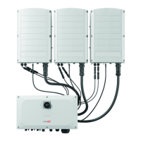
Mounting and Connecting the Synergy Manager and
Synergy Units
This section provides instructions for vertical installation of the inverter and horizontal
Inverter installed horizontally on a flat surface.
NOTE
Make sure the mounting surface or structure can support the weight of 82 kg
(for inverter with two Synergy Units) or 114 kg (for inverter with three Synergy
Units) of the inverter and brackets. Make sure that the mounting surface is at
least 100.8 cm / 39.68” x 114.5 cm / 45".
Chapter 3: Installing the Synergy Manager and Synergy Units42
Three Phase Inverters with Synergy Technology PN: SExxK-xxxxIxxxx
 Loading...


