Step 2: Connecting a PV module to a Power Optimizer
NOTE
Improper wiring may cause electrical faults in a PV system. To avoid electrical
faults, verify proper locking of connectors and avoid cable tension and friction.
Proper planning, materials and installation reduce the risk of electric arcs,
short-circuits and ground faults in the PV system.
NOTE
Images are for illustration purposes only. Refer to the label on the product to
identify the plus and minus input and output connectors.
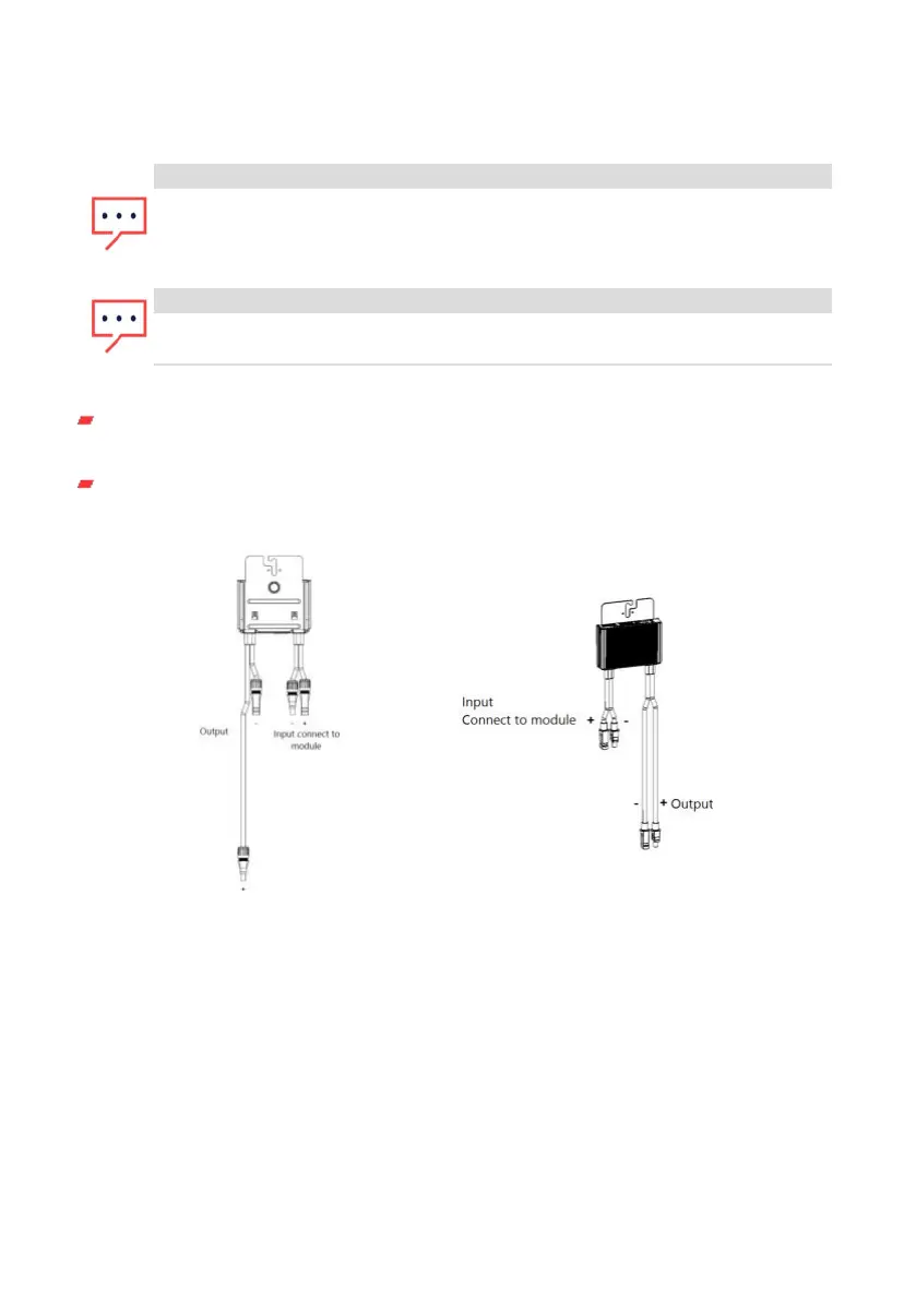
For each of the Power Optimizers:
Connect the Plus (+) output connector of the module to the Plus (+) input connector
of the Power Optimizer.
Connect the Minus (-) output connector of the module to the Minus (-) input
connector of the Power Optimizer.
Figure 7: S-Series (left) and P-Series (right) Power Optimizer connectors
Step 3: Connecting Power Optimizers in PV strings
You can construct parallel PV strings of unequal length, that is, the number of Power
Optimizers in each PV string does not have to be the same. The minimum and
maximum PV string lengths are specified in the power datasheets. Refer to the
SolarEdge Site Designer for PV string length verification.
Chapter 2: Installing the Power Optimizers31
Three Phase Inverters with Synergy Technology PN: SExxK-xxxxIxxxx
 Loading...


