In the inverter (see
Figure 32
):
a. Carefully cut the two cable ties on the DC and RS485 ferrite rings.
b. Disconnect the antenna cable, the RS485 and/or Ethernet connections from the
communication board, then pull them through the inverter openings.
c. Disconnect the DC + and DC - wires, then pull them through the inverter
openings.
In the Connection Unit (see
Figure 32
):
a. Disconnect the grounding (PE) wire.
b. Disconnect the red and black ACwires (see
Figure 32
).
c. Pull the disconnected wires upwards through the openings.
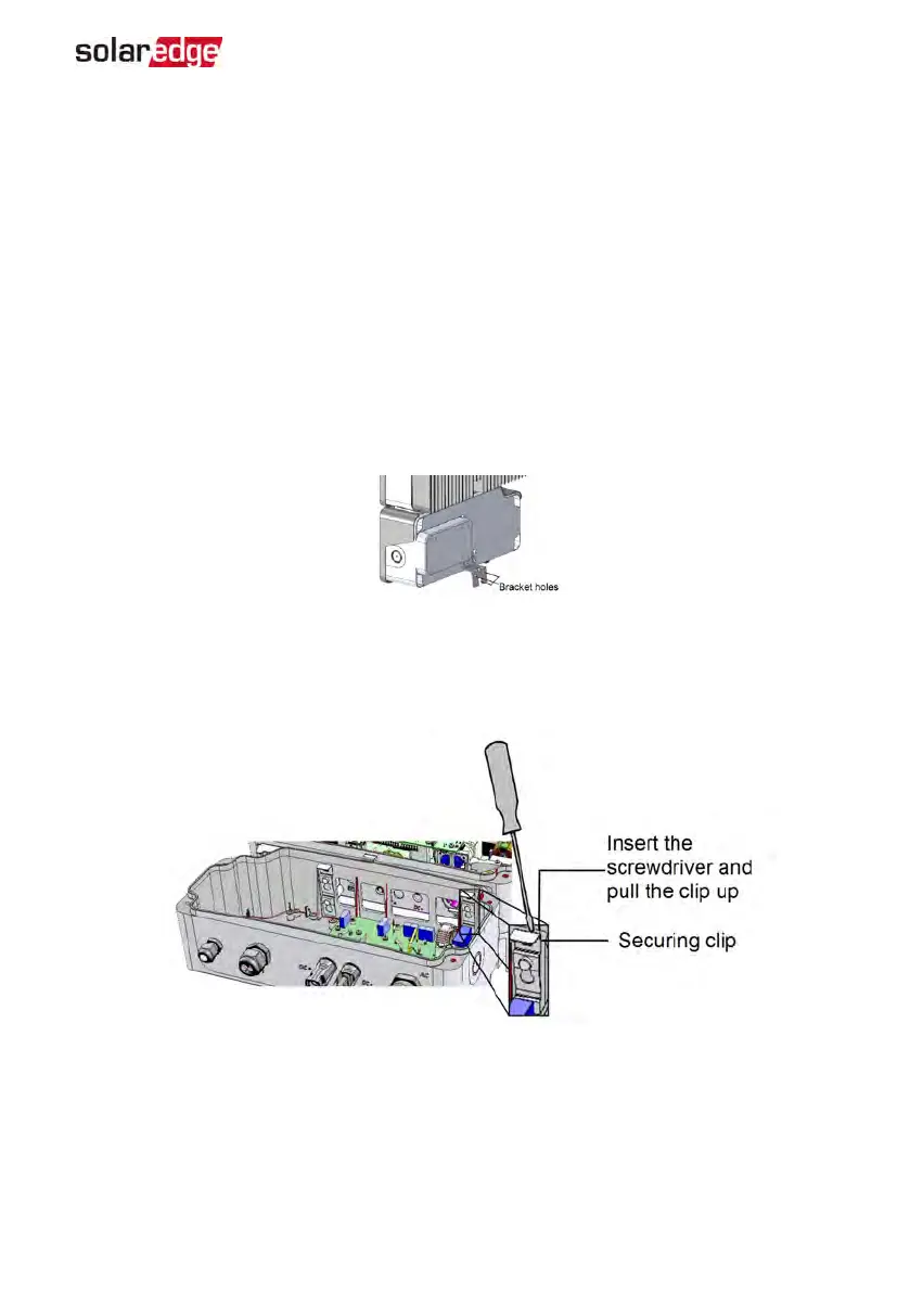
3.
Open the Connection Unit bracket screws.
Figure 33: Connection Unit bracket
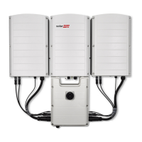
9.
Disconnect the Connection Unit from the inverter by opening the two clips securing
the Connection Unit to the inverter: Carefully place a screwdriver between the clip
and the enclosure and pull the clip.
Figure 34: Disconnecting the Connection Unit from the inverter
10. Detach the Connection Unit from the inverter and place the new one and secure it
to the inverter using the clips.
11.
Reconnect all disconnected cables and wires as they were connected before
Appendix B: Replacing and Adding System Components 75
EV Charging Single Phase Inverter Guide MAN-01-00583-1.5