7828 Density Transmitter Technical Manual Mechanical Installation
78285000_AB 2-11
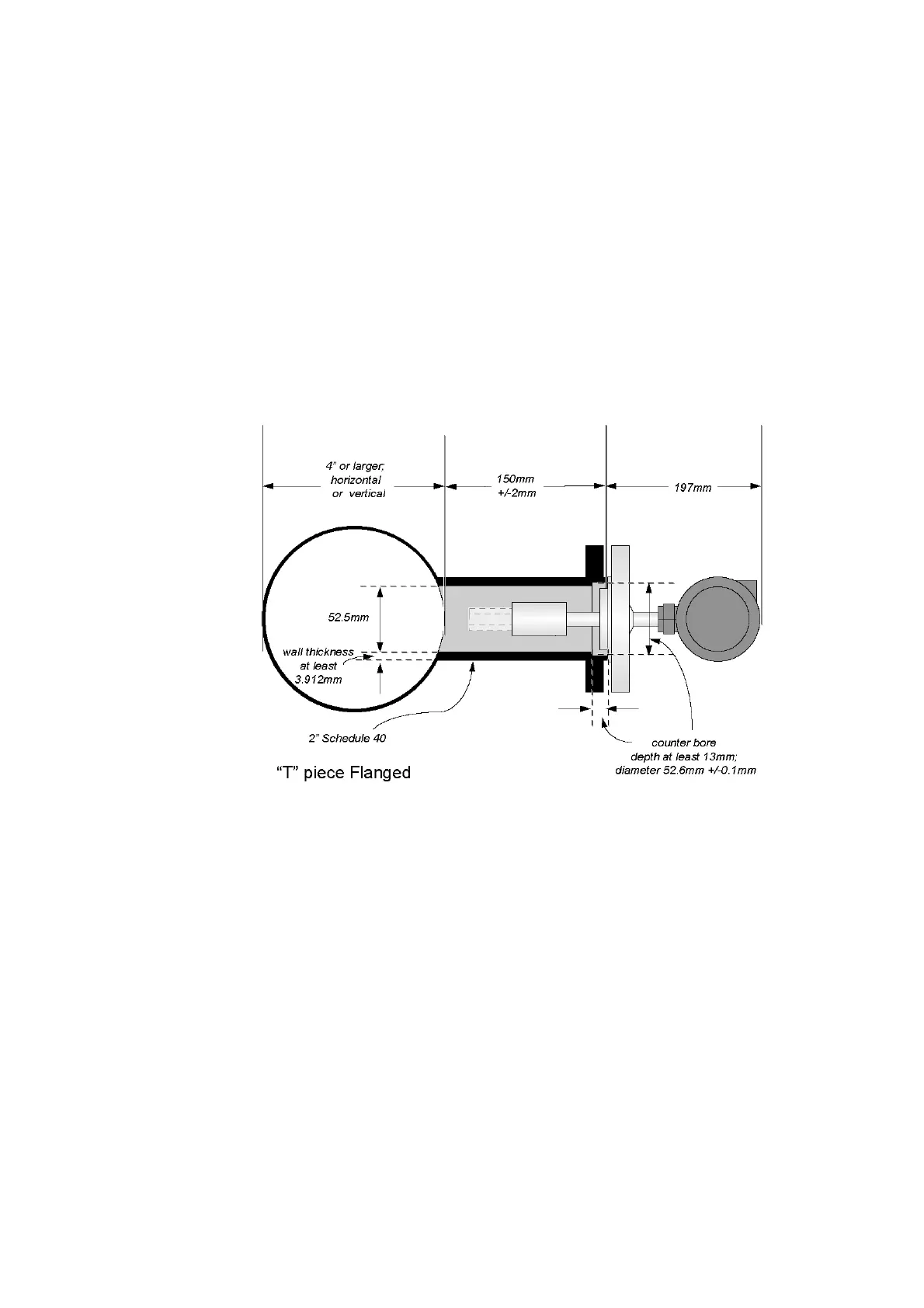
2.3.4 T-PIECE INSTALLATION
Conditions:
Flow: 0.5 to 3.0m/s (at the main pipe wall)
Viscosity: Up to 100cP, or 250cP under some conditions (See section 2.2.2)
Temperature: -50°C to 200°C
The thermal mass of the flanges may affect the response time of the transducer to
temperature changes.
Flow velocity at the pipe wall and fluid viscosity must be within the limits shown to ensure
that the fluid within the pocket is constantly refreshed. This installation will not respond as
rapidly as the free-stream installation to step changes in viscosity.
The view shown is schematic to show the dimensions of the side pocket, which is
fabricated by the end user.
The pocket geometry must be consistent with 2” schedule 40 tube in both internal
diameter and minimum wall thickness, i.e.:
internal diameter: 52.5mm
minimum wall thickness: 3.192mm
Alternatively, schedule 80 or 160 tube may be used, but this affects the calibration, and
must therefore be specified when ordering the sensor.
Counter bore the pocket to a minimum depth of 13mm and diameter 52.6 ±0.1mm to
locate the 7828 centrally.
Weld neck or slip-on flanges may be used, according to the flange rating selected.
However, for higher rated flanges, only slip-on flanges may give the necessary
clearances.
For normal flow conditions (up to 3m/s at the pipewall), the tines should be retracted
25mm from the main pipe wall. For higher flow rates, increase this by 10mm for every
1m/s increase in main flow rate.