Electrical Installation 7828 Density Transmitter Technical Manual
3-4 78285000_AB
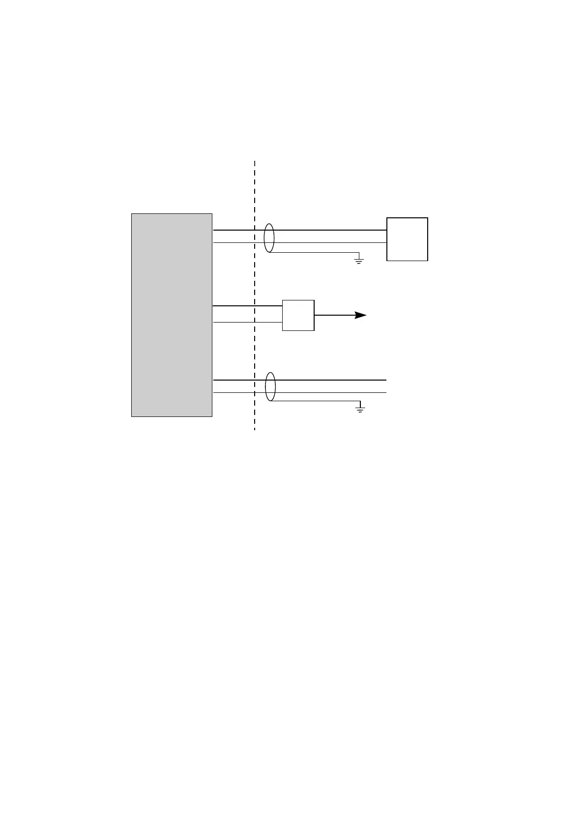
3.3 WIRING THE 7828
The wiring schedule for the 7828 is shown below.
HAZARDOUS AREA SAFE AREA
7828 Density Transmitter
Power +
Power -
RS485 A
RS485 B
4-20mA output +
4-20mA output -
Power supply
(
24V dc at 100mA)
+ 24V
0V
RS485/232
converter
To RS232 port on a PC running
Solartron’s ADView software for
monitoring, maintenance and
configuration.
The 4-20mA analog output loop must
be powered by an external source,
Analog o/p +
Analog o/p -
1
2
4
3
5
6
Notes:
Always conform to local codes of practice and regulations.
The main 24V power supply must supply between 20 and 28V dc at 70mA.
The RS485/232 converter and PC are not normally installed permanently. However it is
strongly recommended that the wiring to the 7828 is made at installation.
The 4-20mA analog output is not self-powered: an external supply is required. The main
power supply can be used for this purpose if appropriate.
Typically, three pairs of shielded 19/0.30mm
2
(#16 AWG) to 19/0.15mm
2
(#22 AWG) wire
are used for wiring.
The naming conventions for RS485 signals differ between manufacturers. If RS485
communications do not function correctly, try swapping the signals over at one end of the
link.