Page 14
Duality SE Installation Guide
System Installation Section 4
10
5
0
5
10
20
30
40
50
∞
10
5
0
5
10
20
30
40
50
∞
10
5
0
5
10
20
30
40
50
∞
10
5
0
5
10
20
30
40
50
∞
10
5
0
5
10
20
30
40
50
∞
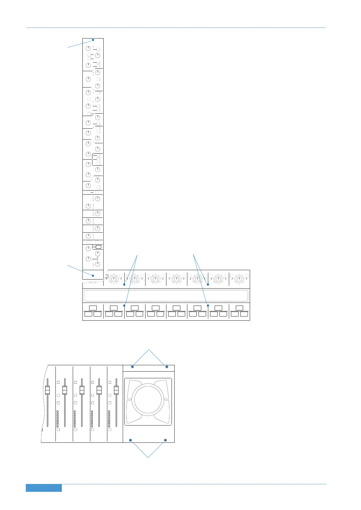
1. Remove 4 x M3 hex-head screws (
AA
)
2. Lift panel up from ends
1. lift the magnetic centre section scribble strip to reveal
the screws (
DD
).
2. Remove the centre section front buffer (p.13) to reveal
the screws (
EE
).
3. Lift trackball assembly up and to the left – caution: the
track ball is not captive.
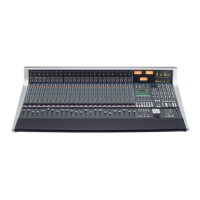
1. Remove Solo & Cut panel (see below).
2
. Remove 1 x M3 hex-head front panel screw (
BB
)
from top
of module. Screw module puller tool into threaded hole.
3
. Remove 1 x M3 cross-head screw (
CC
)
from bottom of
module (beneath Solo Tile).
4. Remove 1 x M3 cross head screw from rear panel (above
X
LR microphone input socket).
5. Pull module upwards from bottom edge using hole in lower
edge and guide with puller at top.
Channel Strip Removal
Solo and Cut Panel Removal
Trackball Panel Removal
A
D
E
C
B
A