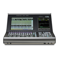
Section Assembly
Before commencing mechanical assembly any necessary modules or panels should be removed. The top trim sections
should also be hinged open.
Make sure that at least six people are available before attempting to move console sections. Ensure all parts are supported
a
dequately – a strong stand (such as a stool or trolley) of approximately 420mm high will be extremely useful to support
the un-supported end of the console whilst the sections are aligned.
Before the sections can be joined, they must be horizontal and at the same height.
Locate the insert parts needed for reassembly of the beam. (These parts will usually be assembled and slid into one of the
beam sections – loosening all eight of the M10 bolts will allow the plate and inserts to slide along to the beam joint).
Position the plate and inserts at the joint so that approximately half of the insert is visible. Hand tighten the bolts.
Align the two console sections so that the beam inserts are in the correct position on the opposing beam. It may be
necessary to remove four of the bolts. If particularly awkward then remove all eight bolts and the securing plate.
Carefully push the two console sections together. If the sections are aligned correctly, the inserts should slide into place
with minimal force – they are not a tight fit.
Take particular care that the buscard linking ribbons and the meter cable are not snagged or crushed when positioning
the frame sections.
Fit any remaining M10 bolts and hand tighten checking that the inserts are still positioned with half in each section. Tighten
sufficiently so that the joint is secure and the sections will not slide apart. Some adjustment may still be necessary until all
screws are in place.
Although stitching screws can be fitted from either side of the profile they are usually inserted through the left profile to
screw into the right-hand side. The exception will be at the Centre section split where three of the screws are be inserted
from, the right – thus eliminating the need to remove Master section panels.
Before inserting the nine off ‘stitching’ screws check that the profiles are touching all round with no gaps; do not use the
M3.5 screws to pull the two sections together
One by one, insert the nine off M3.5 ‘stitching’ screws through the LH profile and loosely fix into the corresponding holes
in the RH profile. Secure each screw by a few turns only until all nine are located.
Gradually tighten the screws a few turns at a time checking that the profile edges are correctly aligned. Only tighten the
screws completely once alignment is correct.
Now fully tighten each of the M10 bolts in the beam plate.
Page 17
Duality SE Installation Guide
Section 4 System Installation
 Loading...
