17
Copyright © 2015 Somfy SAS. All rights reserved.
EN
Images not contractually binding
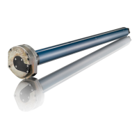
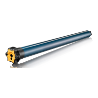
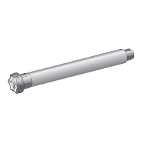
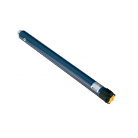
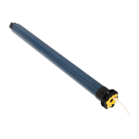
2. 1. 3. Drive/tube assembly
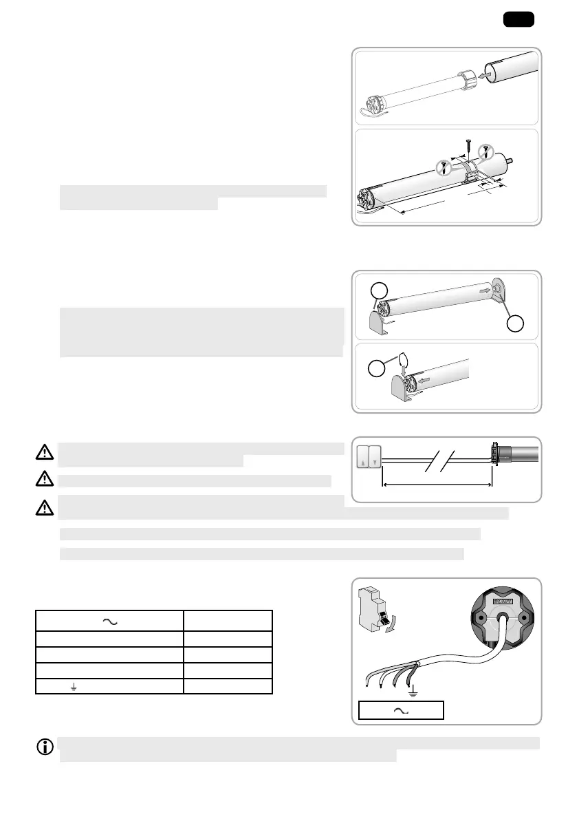
1) Slide the motor into the roller tube.
For roller tubes which are smooth inside, position the
notch previously cut on the boss on the crown.
2) The drive wheel must be locked in place to prevent it moving
along the roller tube:
• This can be done either by fixing the roller tube to the drive
wheel using 4 x Ø 5 mm self-tapping screws, or by using
4 x Ø 4.8 mm steel pop rivets placed 5 mm to 15 mm from
the outer rim of the drive wheel, regardless of the roller
tube.
1
The screws or pop rivets must only be attached to the
drive wheel and not to the drive.
• Alternatively, a drive wheel stop can be used for tubes
which are not smooth.
2. 1. 4. Installing the drive/tube assembly
1) Install and fi x the tube/drive assembly onto the end bracket
f and onto the drive bracket g:
1
Ensure that the drive/tube assembly is secured onto the
end bracket. This operation prevents the drive/tube
assembly from coming out of the end bracket mounting
when the roller blind reaches the lower end limit position.
2) Depending on the type of bracket, fit the stop ring h
in place.
2. 2. WIRING
Cables which pass through a metal wall must be protected
and isolated using a sheath or sleeve.
Attach cables to prevent any contact with moving parts.
If the drive is used outdoors, and if the supply cable is a
type HO5-VVF cable, the cable should be installed in a UV-resistant duct, e.g. under a gland.
1
Leave the drive power supply cable accessible: it must be possible to replace it easily.
1
Always make a loop in the power supply cable to prevent water entering the drive!
- Switch off the power supply.
- Connect the drive according to the information in the table
below:
230 V 50 Hz Cable
Neutral (N) Blue
Live, direction 1 (L1) Brown
Live, direction 2 (L2) Black
Earth (
)Yellow/Green
D e p e n d i n g o n t h e m a x i m u m l o a d c u r r e n t o f t h e c o n t r o l p o i n t a n d d e p e n d i n g o n t h e t y p e s o f m o t o r s ,
several motors can be connected in parallel to a single control point.
15 mm
5 mm
20 mm
L1
1)
2)
1)
2)
h
g
f
L ≤ 50 m
230 V 50 Hz
N L1 L2
OFF
 Loading...