Page 8
bearings. The exact water temperature and flow required in the cooling circuit
will vary with each blower configuration and application. Although water
demand for the blower head varies, the common design point in all applications is
that the water exiting from the cooling circuit should never exceed 100°F (38°C).
Typical water demand will range from ¼ to ¾ gallons per minute (1 to 3 liters per
minute) if using tap water (approximately 65°F (18°C)) and will be significantly
lower if chilled water is used.
4.2.9 Thermocouple Option
All Sonic 150 blower heads can be ordered with a thermocouple option. The
thermocouple is in direct contact with the shaft bearing and continuously monitors
the temperature of the bearing. Continuous monitoring of the blower head bearing
temperature can indicate an imminent bearing failure (See Section 12 for Sonics’
repair policy). Predicting and anticipating a bearing failure may save costly
equipment and / or line down time.
4.3 Belt Installation
Sonic ships all new systems with the drive belt removed. This is to assure that the
electrical starter, soft start and wiring is correct before the blower is started. See Section
5.1 for motor wiring instructions and verify that the wiring and blower rotation is correct
before installation of the drive belt.
4.3.1 Tools Required
¾ inch deep socket (optional)
4.3.2 Belt Installation Procedure
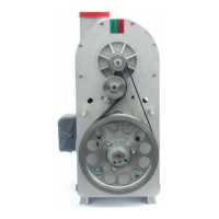
1. Remove the belt guard using the 1/2 inch socket. (See Figure 6)
2. Using the 9/16 inch box-end wrench, rotate the belt tensioner arm counter
clockwise (CCW). At the same time wrap the belt around the blower pulley, then
along the right side of the idler pulley, and finally around the motor pulley. (See
Figure 7)
3. Slowly rotate the motor pulley to make sure the belt is seated in the grooves.
4. Verify that the belt gap is approximately ¾ inch ±1/16 inch (Factory Set). (See
Figure 8)
5. If a ¾ inch belt gap was not achieved, use a ¾ inch deep socket to loosen the
bracket mounting screws behind the motor pulley and slide the bracket. (See
Figure 9 and Figure 10)
6. Using the 1/2 inch socket, reinstall the belt guard.