Page 32
7.4 Belt Tensioner Service
7.4.1 Tools Required
#3 Drive Extension (optional)
¾ inch deep socket (optional)
7.4.2 Belt Tensioner Service Procedure
1. Remove the belt guard using the 1/2 inch socket. (See Figure 42)
2. Using the 9/16 inch box-end wrench, rotate the belt tensioner arm counter
clockwise (CCW) and remove the belt. (See Figure 43)
3. Use the ¾ inch deep socket to hold the motor pulley in place. Using the 5/16 inch
allen socket, remove the motor pulley screws and motor pulley. (See Figure 44)
4. Using the 3/16 inch allen wrench, secure the flat head screw from the back of the
bracket while loosening the nylon-insert locknut with a ½ inch socket. This will
allow the removal of the belt tensioner. (See Figure 45 and Figure 46)
5. Caution: After removing belt tensioner, the compression springs will be exposed.
Remove these springs temporarily if the new belt tensioner is not installed
immediately. Wear safety glasses to prevent potential eye injury. (See Figure 47)
6. At reassembly, the static position should be approximately 25 degrees to the right
of blower pulley. Install a new nylon-insert locknut to 20 ft-lbs when installing
the new belt tensioner. (See Figure 48)
7. Using the 9/16 inch box-end wrench, rotate the belt tensioner arm counter
clockwise (CCW). At the same time wrap the belt around the blower pulley, then
along the right side of the idler pulley, and finally around the motor pulley.
8. Slowly rotate the motor pulley to make sure the belt is seated in the grooves.
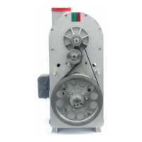
9. Verify that the belt gap is approximately ¾ inch (Factory Set). (See Figure 49)
10. If a ¾ inch belt gap was not achieved, use a ¾ inch deep socket to loosen the
bracket mounting screws behind the motor pulley and slide the bracket. (See
Figure 50 and Figure 51)
11. Using the 1/2 inch socket, reinstall the belt guard.