6-16
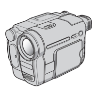
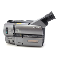
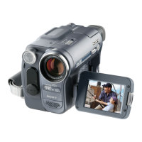
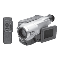
CCD-TRV138/TRV238E/TRV338/TRV438E
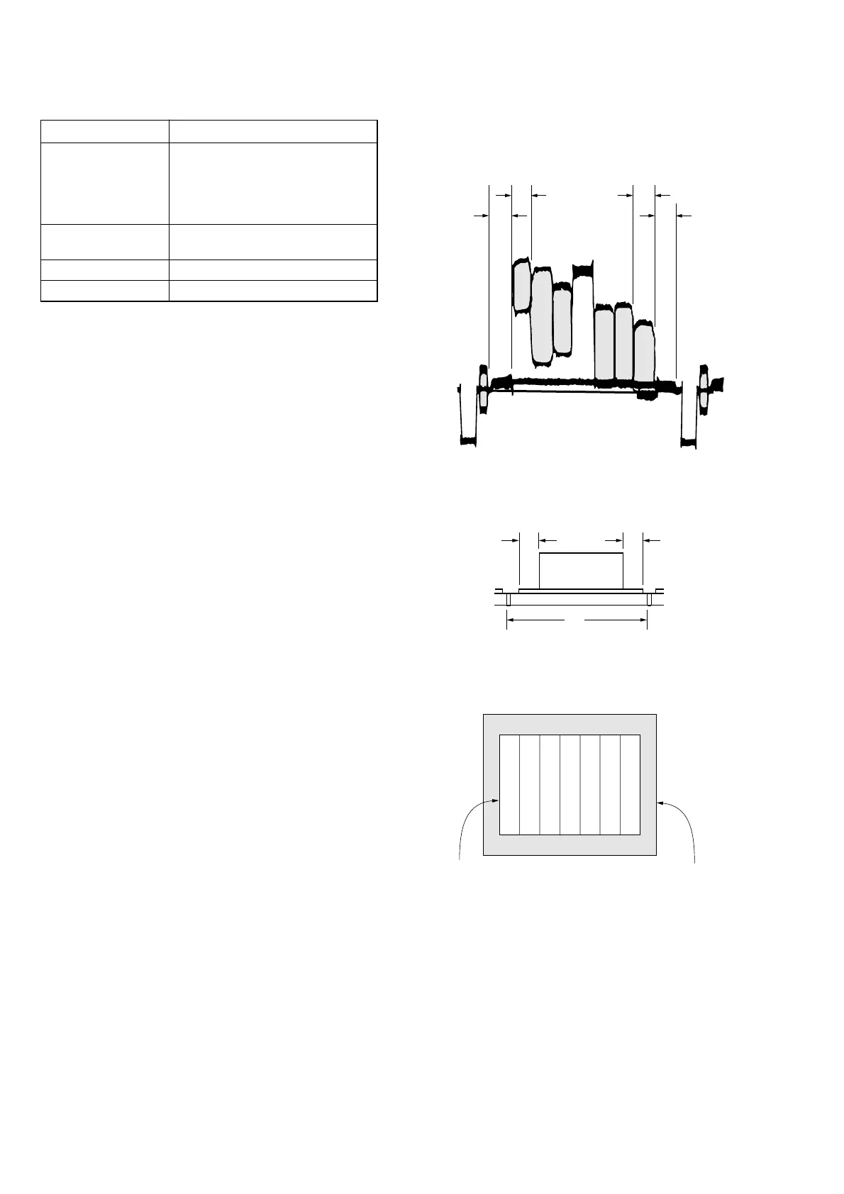
Check on the oscilloscope
1. Horizontal period
A=B
C=D
A
BC
D
Color bar chart picture frame
Monitor TV picture frame
Fig. 6-1-9
2. Vertical period
Fig. 6-1-10
Check on the monitor TV (Underscanned mode)
Fig. 6-1-11
6. Picture Frame Setting
Mode CAMERA
Subject Color bar chart
(Color reproduction adjustment
frame)
(1 m (PTB-450) or 40 cm (PTB-
1450) from the front of lens)
Measurement Point Video terminal of A/V OUT jack
(75 Ω terminated)
Measuring Instrument Oscilloscope and monitor TV
Specified Value A=B, C=D, E=F
Note 1: Check that the data of page: 0, address: 10 is “00”.
Note 2: Perform “Flange Back Adjustment” and “Optical Axis
Adjustment” before this adjustment.
Switch setting:
1) DIGITAL ZOOM (Menu setting) .................................... OFF
2) STEADYSHOT (Menu setting)
(CCD-TRV338/TRV438E only) ...................................... OFF
3) DISPLAY (Menu setting) ................................................LCD
Setting method:
1) Select page: 6, address: 48, and set data: 01.
2) Adjust the zoom and the camera direction, and set to the speci-
fied position.
3) Mark the position of the picture frame on the monitor display,
and adjust the picture frame to this position in following ad-
justments using “Color reproduction adjustment frame”.
Processing after completing camera system adjustments:
1) Select page: 6, address: 48, and set data: 00.