6-30
CCD-TRV138/TRV238E/TRV338/TRV438E
3-4. VIDEO SYSTEM ADJUSTMENTS
Before perform the video system adjustments, check that the data
of page: 0, address: 10 is “00”.
If not, select page: 0, address: 10, and set the data “00”.
Video system adjustments must be performed in the following or-
der.
Adjusting procedure:
1. 28 MHz origin oscillation adjustment
2. AFC f
0
adjustment
3. LINE OUT level adjustment
4. REC Y current adjustment
5. REC C/AFM current adjustment
1. 28 MHz Origin Oscillation Adjustment
(VC-341 Board)
Set the frequency of the clock for synchronization.
If deviated, the synchronization will be disrupted and the color
will become inconsistent.
Mode VTR stop (PLAY/EDIT mode)
Signal No signal
Measurement Point Pin qa of IC151
Measuring Instrument Frequency counter
Adjustment Page F
Adjustment Address 10
Specified value f = 14318181 ± 68 Hz (NTSC model)
f = 14187500 ± 54 Hz (PAL model)
Note 1: Check that the data of page: 0, address: 10 is “00”.
Note 2: Refer to “2. DISASSEMBLY”, when opening the VC-
341 board.
Adjusting method:
Order Page Address Data Procedure
10 0101
2F 10
Change the data and set the
frequency (f) to the specified
value.
3F 10 Press PAUSE button.
40 0100
Fig. 6-3-4
2. AFC f
0
Adjustment (VC-341 Board)
RadarWRadarWRadarW
Adjust the pull-in range of A/D converted clock generator during
playback.
Mode VTR stop (PLAY/EDIT mode)
Signal No signal
Measurement Point Displayed data of page: 3, address: 03
Measuring Instrument Adjusting remote commander
Adjustment Page C
Adjustment Address 19
Specified value The data of page: 3, address: 03 is “00”
Note 1: Check that the data of page: 0, address: 10 is “00”.
Adjusting method:
Order Page Address Data Procedure
1
Close the cassette compartment
without inserting cassette.
20 0101
33 01 82 Press PAUSE button.
43 02
Check the data changes to
“00”.
53 03
Check that the data is “00”.
(Note 2)
60 0100
Note 2: If the data is other than“00”, adjustment has errors.
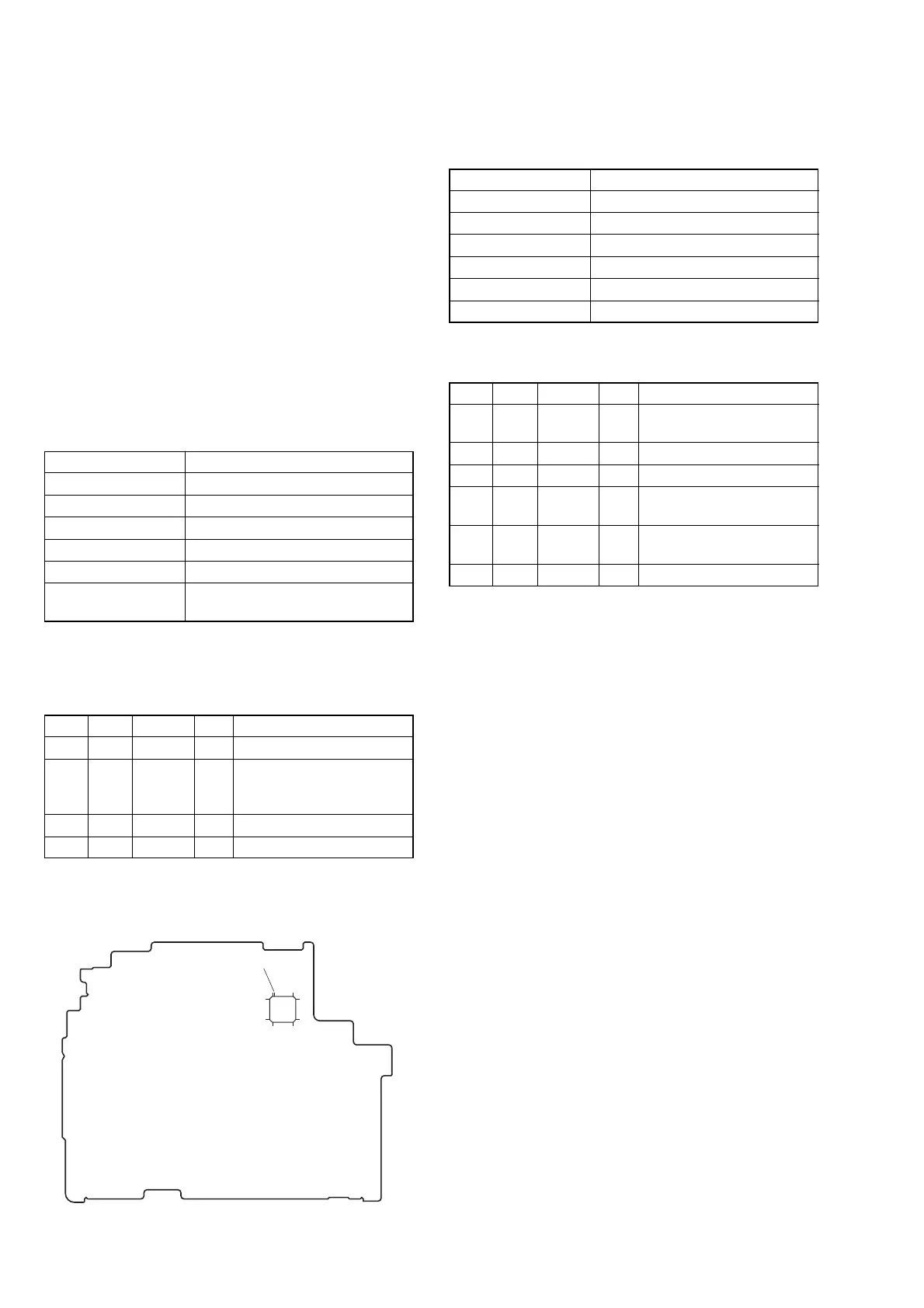
IC151
13
12
11 1
3625
24
48
37
Measurement
Point
VC-341 BOARD (SIDE B)