6-35
CCD-TRV138/TRV238E/TRV338/TRV438E
3-5. AUDIO SYSTEM ADJUSTMENTS
Before performing the audio system adjustments, check that the
data of page: 0, address: 10 is “00”.
If not, select page: 0, address: 10, and set data “00”.
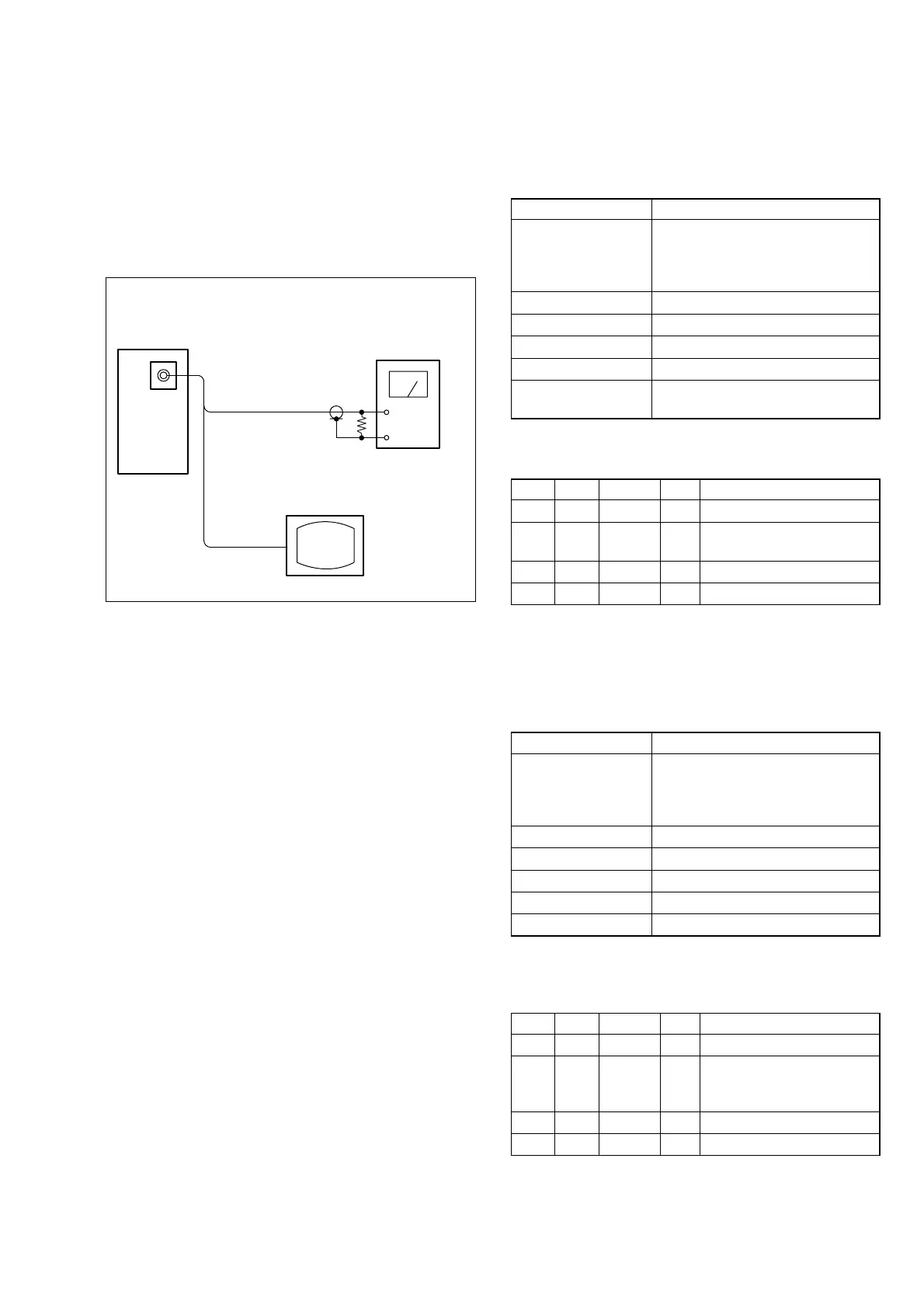
[Connecting the measuring instruments for the audio]
Connect the audio system measuring instruments in addition to
the video system measuring instruments as shown in Fig. 6-3-9.
Fig. 6-3-9
Main unit
47 kΩ
47 kΩ: 1-249-437-11
Audio level meter
or distortion meter
TV monitor
A/V OUT
jack
Video
Audio
In Playback
1. BPF f
0
Adjustment (VC-341 Board)
Set the BPF passing frequency of IC801 so that the AFM signal
can separate from the playback RF signal properly. If deviated,
the noises and distortions will increase during high volume play-
back.
Mode VTR playback (PLAY/EDIT mode)
Signal Alignment tape
For BPF adjustment
(WR5-11NS (NTSC))
(WR5-11CS (PAL))
Measurement Point Audio terminal of A/V OUT jack
Measuring Instrument Distortion meter
Adjustment Page C
Adjustment Address 30
Specified value The distortion rate should be
minimum.
Note: Check that the data of page: 0, address: 10 is “00”.
Adjusting method:
Order Page Address Data Procedure
10 0101
2C 30
Change the data and minimize
the distortion rate.
3C 30 Press PAUSE button.
40 0100
2. 1.5 MHz Deviation Adjustment (VC-341 Board)
Adjust to the optimum 1.5 MHz audio FM signal deviation.
If the adjustment is not correct, its playback level will differ from
that other units.
Mode VTR playback (PLAY/EDIT mode)
Signal Alignment tape
For checking operation
(WR5-5NSP (NTSC))
(WR5-5CSP (PAL))
Measurement Point Audio terminal of A/V OUT jack
Measuring Instrument Audio level meter
Adjustment Page C
Adjustment Address 2F
Specified value –7.5 ± 2.0 dBs
Note 1: Check that the data of page: 0, address: 10 is “00”.
Note 2: Perform “BPF f
0
Adjustment” before this adjustment.
Adjusting method:
Order Page Address Data Procedure
10 0101
2C 2F
Change the data and set the
400 Hz audio signal level to
the specified value.
3C 2F Press PAUSE button.
40 0100