6-26
CCD-TRV138/TRV238E/TRV338/TRV438E
CN007
A/V OUT jack
16
1
Audio (black)
Video (yellow)
TV monitor
AC adaptor
AC IN
AC adaptor
CPC lid
Screw (M2)
I/F unit for LANC control
(J-6082-521-A)
CPC jig connector
(J-6082-539-A)
L serices Info
LITHIUM battery (7.2Vdc)
Adjustment
remote commander (RM-95)
Conductor side
LANC jack
AC IN
3-1-2. Precautions on Adjusting
This set is adjusted in two modes, VTR mode and CAMERA mode.
3-1-3. Adjusting Connectors
Some of the adjusting points of the video section are concentrated
at VC-341 board CN007. Connect the measuring instruments via
I/F unit for LANC control (J-6082-521-A) and CPC jig connector
(J-6082-539-A).
The following table shows the pin No. and signal name of CN007.
Pin No. Signal Name Pin No. Signal Name
1 EEP SCK 9 PB RF
2 PB RF 10 REG GND
3 BPF MONI 11 LANC OUT
4 CAP FG 12 LANC IN
5 SWP DIR 13 XLANC PWR ON
6 REG GND 14 EEP SO
7 REC RF 15 EEP SI
8 REG GND 16 XCS EEP
Table 6-3-1
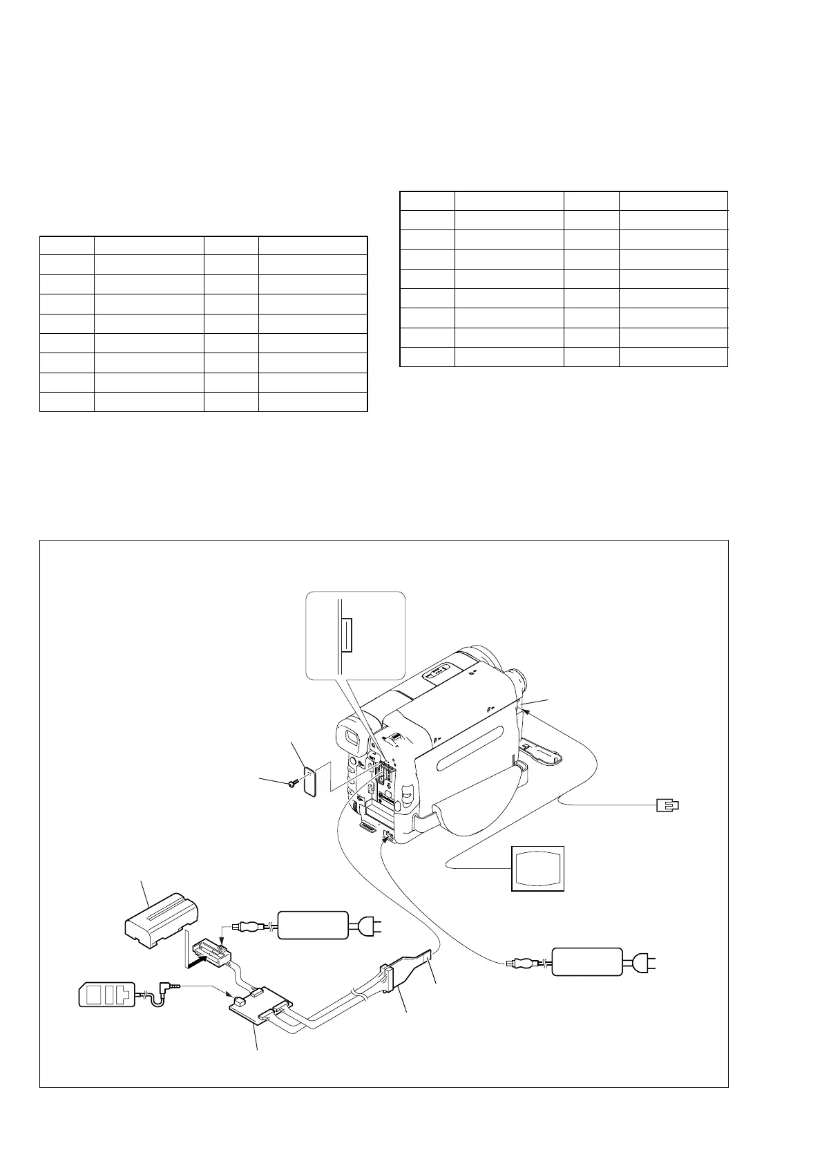
Connecting the TV Monitor and Adjustment Remote Commander
Fig. 6-3-1
Note: Use either the AC power adaptor or the InfoLITHIUM battery as the power supply of I/F unit for LANC control.
The following table lists the test point of I/F unit of for LANC
control.
Pin No. Signal Name Pin No. Signal Name
BL 15 EVF VCO
14 EVF VG BL 4.75
9 PB RF (MON)
3 BPF MONI 6, 8, 10 GND
TMS 7 REC RF (RF IN)
TDI TDO
5SWP TCK
4 CAP FG 2 IR VIDEO
Note: Pin No. are those of CN007.
Table 6-3-2
3-1-4. Connecting the Equipment
Connect the measuring instruments as shown in Fig. 6-3-1 and
perform the adjustments.