6-32
CCD-TRV138/TRV238E/TRV338/TRV438E
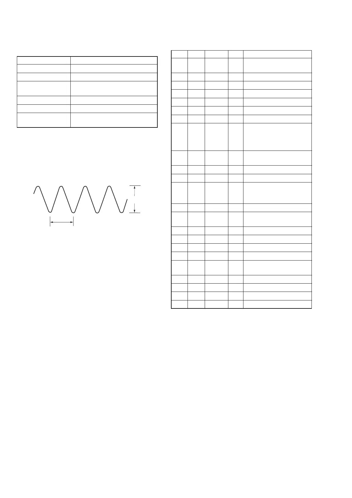
4. REC Y Current Adjustment (VC-341 Board)
Adjust the Y FM signal recording current.
Mode VTR recording (PLAY/EDIT mode)
Signal No signal
Measurement Point REC RF (Pin 7 of CN007)
Measuring Instrument Oscilloscope
(20 MHz BW LIMIT: OFF)
Adjustment Page C
Adjustment Address 1E, 1F
Specified value A = 235 ± 5 mVp-p (NTSC)
A = 280 ± 5 mVp-p (PAL)
Note 1: Check that the data of page: 0, address: 10 is “00”.
Note 2: Don’t disconnect the DC power supply of camcoder dur-
ing the following adjustments.
When the following symptom occurs, reset the data of A
page to the values note down.
1) The power is shut off so that unit can not operate.
Fig. 6-3-6
A
0.18 µsec
Adjusting method:
Order Page Address Data Procedure
1
Close the cassette compartment
without inserting cassette.
2 Set to the VTR stop mode.
30 0101
4C 14 01 Press PAUSE button.
5A 10 10 Press PAUSE button.
67 10 02 Press PAUSE button.
7A 1A Note down the data.
8A 1A
Set the following data, and
press PAUSE button.
06: NTSC model
26: PAL model
9
Set to the VTR recording
mode. (Note 3)
10 3 92 10
11 3 01 41 Press PAUSE button.
12 C 1F
Change the data and set the
REC Y signal level (A) to the
specified value.
13 C 1F Press PAUSE button.
14 C 1F
Read the data, and this data is
named D
1F
.
15 C 1E D
1F
Press PAUSE button.
16 3 01 00 Press PAUSE button.
17 3 92 00
18 Set to the VTR stop mode.
19 A 1A
Set data noted down at step 7,
and press PAUSE button.
20 7 10 E2 Press PAUSE button.
21 A 10 00 Press PAUSE button.
22 C 14 00 Press PAUSE button.
23 0 01 00
Note 3: Use the REC buttons of the adjustment remote com-
mander (with HOLD switch set in the OFF position).