6-33
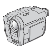
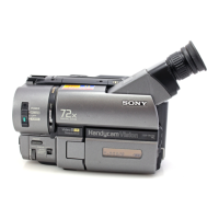
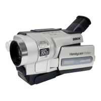
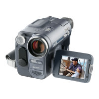
CCD-TRV138/TRV238E/TRV338/TRV438E
5. REC C/AFM Current Adjustment
5-1. Preparations
Note 1: Check that the data of page: 0, address: 10 is “00”.
Order Page Address Data Procedure
1
Close the cassette compartment
without inserting cassette.
2 Set to the VTR stop mode.
30 0101
4C 14 01 Press PAUSE button.
5A 10 10 Press PAUSE button.
67 10 02 Press PAUSE button.
7A 1A Note down the data.
8A 1A
Set the following data, and
press PAUSE button.
06: NTSC model
26: PAL model
Note 2: Don’t disconnect the DC power supply of camcoder dur-
ing the following adjustments.
When the following symptom occurs, reset the data of A
page to the values note down.
1) The power is shut off so that unit can not operate.
5-2. REC C Current Check (VC-341 Board)
Check the recording current level of the REC chroma signal.
If it is too low, chroma signal noise in playback picture will be
increased. If too high, Y signal noises will increase and white
modulation noises will be produced.
Mode VTR recording (PLAY/EDIT mode)
Signal No signal
Measurement Point REC RF (Pin 7 of CN007)
Measuring Instrument Oscilloscope
(20 MHz BW LIMIT: OFF)
Specified value A = 50.8 ± 3.0 mVp-p (NTSC)
A = 54.0 ± 3.0 mVp-p (PAL)
Note 1: Check that the data of page: 0, address: 10 is “00”.
Checking method:
Order Page Address Data Procedure
1
Close the cassette compartment
without inserting cassette.
2
Set to the VTR recording
mode. (Note 2)
30 0101
43 9130
53 9220
6C 25 Note down the data.
7C 25 00 Press PAUSE button.
83 01 41 Press PAUSE button.
9
Check that the REC chroma
signal level (A) satisfies the
specified value, and note
down the signal level.
10 3 01 00 Press PAUSE button.
11 C 25
Set data noted down at step 6,
and press PAUSE button.
12 3 91 00
13 3 92 00
14 0 01 00
15
Perform “REC AFM Current
Adjustment” and “Processing
after Completed Adjustment”.
Note 2: Use the REC buttons of the adjustment remote com-
mander (with HOLD switch set in the OFF position).
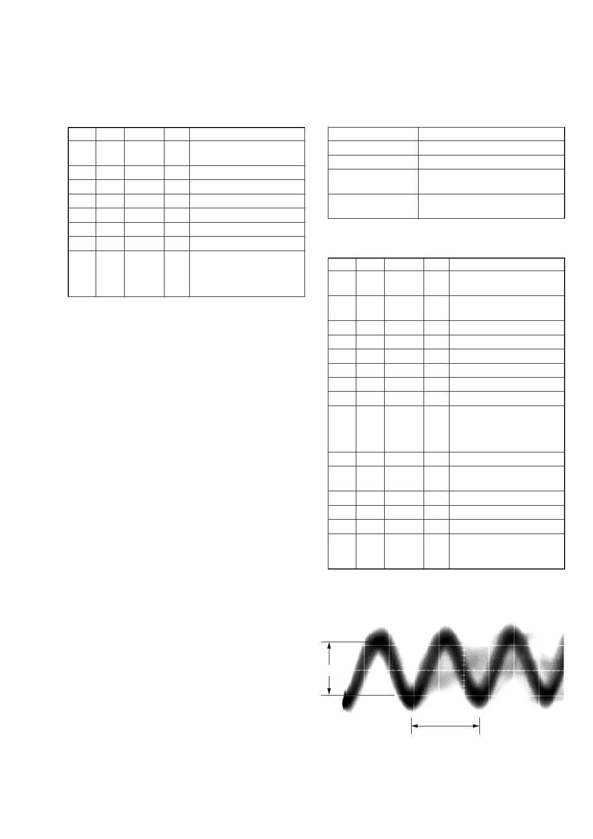
Fig. 6-3-7
A
1.35 µsec
Center of the luminance line width