6-29
CCD-TRV138/TRV238E/TRV338/TRV438E
3-2. SYSTEM CONTROL SYSTEM ADJUSTMENTS
1. Initialization of 8, A, C, D, E, F, 1F Page Data
If the 8, A, C, D, E, F, 1F page data is erased due to some reason,
perform “1-2. INITIALIZATION OF 8, A, C, D, E, F, 1F PAGE
DATA” of “6-1. CAMERA SECTION ADJUSTMENTS”.
3-3. SERVO SYSTEM ADJUSTMENTS
Before perform the servo system adjustments, check that the speci-
fied values of “28 MHz Origin Oscillation Adjustment” of “VIDEO
SYSTEM ADJUSTMENTS” is satisfied.
Check that the data of page: 0, address: 10 is “00”.
If not, select page: 0, address: 10, and set the data “00”.
1. CAP FG Offset Adjustment (VC-341 Board)
RadarW
RadarW
RadarW
Set the CAP FG signal duty cycle to 50% to establish an appropri-
ate capstan servo. If deviated, the uneven rotation of capstan and
noise can occur in the playback mode.
Mode VTR stop (PLAY/EDIT mode)
Signal No signal
Measurement Point Displayed data of page: 3, address: 03
Measuring Instrument Adjusting remote commander
Adjustment Page C
Adjustment Address 18
Specified value The data of page: 3, address: 03 is “00”
Note 1: Check that the data of page: 0, address: 10 is “00”.
Adjusting method:
Order Page Address Data Procedure
1
Close the cassette compartment
without inserting cassette.
20 0101
33 01 81 Press PAUSE button.
43 02
Check the data changes to
“00”.
53 03
Check that the data is “00”.
(Note 2)
60 0100
Note 2: If the data is other than “00”, adjustment has errors.
For the error contents, see the following table.
Data of page: 3,
Error contents
address: 03
01 Adjustment time out
10
Mechanism mode error (For example, the
adjustment is performed in the mode except
for VTR stop mode.)
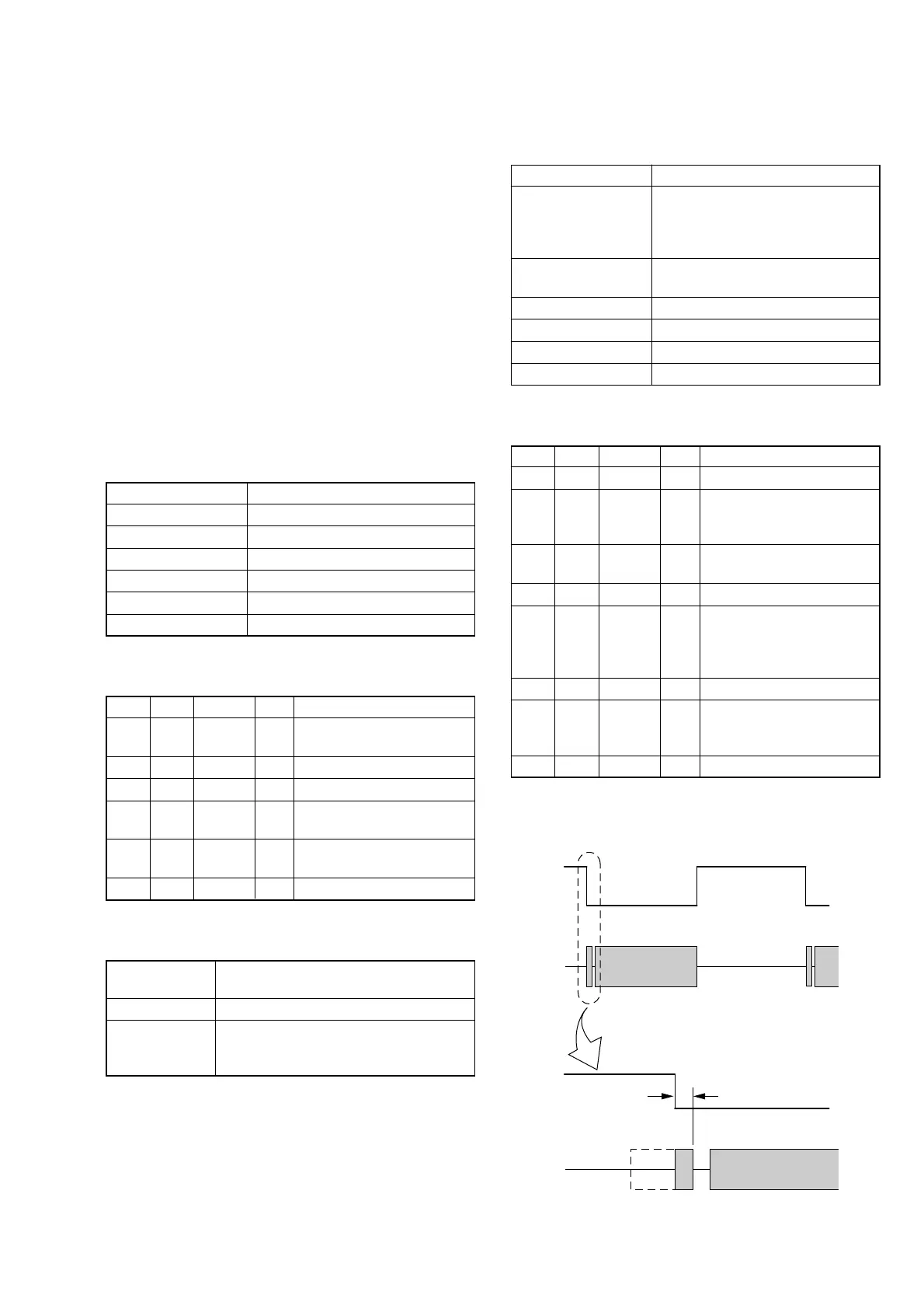
2. Switching Position Adjustment (VC-341 Board)
If deviated in this case cause switching noise or jitter on the played
back screen.
Mode VTR playback
Signal Alignment tape:
For tracking adjustment
(WR5-1NU (NTSC))
(WR5-1CU (PAL))
Measurement Point CH1: SWU (Pin 5 of CN007)
CH2: PB RF (Pin 9 of CN007)
Measuring Instrument Oscilloscope
Adjustment Page C
Adjustment Address 16, 17
Specified value t1 = 0 ± 10 µsec
Note 1: Check that the data of page: 0, address: 10 is “00”.
Adjusting method:
Order Page Address Data Procedure
10 0101
23 92
Set the bit value of bit 2 to “1”,
and press PAUSE button.
(Note 2)
3C 16
Change the data and minimize
“t1”. (Coarse adjustment)
4C 16 Press PAUSE button.
5C 17
Change the data and adjust so
that the switching position (t1)
becomes specified value. (Fine
adjustment)
6C 17 Press PAUSE button.
73 92
Set the bit value of bit 2 to “0”,
and press PAUSE button.
(Note 2)
80 0100
Note 2: For the bit values, refer to “6-4. SERVICE MODE”, “4-
3. 3. Bit Value Discrimination”.
Fig. 6-3-3
CH1
CH2
Enlargement
t1=0 ± 10 µsec
CH1
CH2