EasyManua.ls Logo

Sony CDP-XA50ES Service Manual

Sony CDP-XA50ES
54 pages
To Next Page IconTo Next Page
Page #1 background imageLoading...
Page #1 background image
MICROFILM
CDP-XA50ES
AEP Model
E Model
SERVICE MANUAL
COMPACT DISC PLAYER
Model Name Using Similar Mechanism NEW
CD Mechanism Type
CDM32BB-12B (BLACK)
CDM32BN-12B (GOLD)
Base Unit Name BU-12B
Optical Pick-up Name KSS-273B/J1N
SPECIFICATIONS
Photo: Black
– Continued on next page –

Table of Contents

Other manuals for Sony CDP-XA50ES

Question and Answer IconNeed help?

Do you have a question about the Sony CDP-XA50ES and is the answer not in the manual?
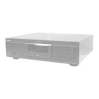
Sony CDP-XA50ES Specifications

General IconGeneral
TypeCD Player
Digital-to-Analog Converter1-bit D/A converter
Frequency Response2 Hz - 20 kHz
Signal-to-Noise Ratio115 dB
Output Level/Voltage2.0 V
Digital outputsCoaxial, Optical
Analog outputsRCA
Dynamic range100 dB
Channel separation110 dB
Disc formatCD

Summary

SAFETY-RELATED COMPONENT WARNING!!

SECTION 1 SERVICING NOTES

Handling Optical Components and Laser Safety

Guidelines for safely handling optical parts and laser diode emission, including cautions.

Basic Operations

Playing a CD

Step-by-step guide on how to play a compact disc.

Playing CDs

Recording From CDs

Recording by Tape Length (Time/Just Edit)

Programming tracks to fit a specific tape length using Time Edit or Just Edit.

Storing Information About CDs (Custom Files)

Indexing a Disc (Custom Index)

Marking specific points on a disc for quick access during playback.

Storing Specific Tracks (Delete Bank)

Saving a selection of desired tracks for playback without manual selection each time.

Playing from Custom Index Points

Instructions for playing a disc using previously set custom index points.

SECTION 3 DISASSEMBLY

LOADING PANEL SECTION

Step-by-step instructions for disassembling the loading panel section.

CASE (TOP PLATE), FRONT PANEL SECTION

AUDIO BOARD

MECHANISM DECK (CDM32BB-12B/CDM32BN-12B)

SERVO BOARD

PANEL (DRAWER)

BASE UNIT (BU-12B)

SLED MOTOR (M21), OPTICAL PICK-UP (KSS-273B/J1N)

SECTION 4 TEST MODE

4-1. AF MODE Operations

Procedure for activating and checking the AF mode, including indicator and key checks.

4-2. ADJ MODE Operations

Procedure for activating and operating the ADJ mode with button functions.

4-3. CLV-S MODE Operation

Procedure for operating the CLV-S mode for spindle servo.

SECTION 5 ELECTRICAL ADJUSTMENTS

S-Curve and E-F Balance Check

Procedures to check and adjust S-curve and E-F balance waveforms.

RF Level and PLL Frequency Checks

Procedures to check RF signal level and PLL free-run frequency.

Skew Adjustment

6-9. IC PIN FUNCTION DESCRIPTION

SERVO BOARD IC201 CXP84124-068Q Pin Functions

SERVO BOARD IC201 CXP84124-068Q (Continued)

SECTION 7 EXPLODED VIEWS

(1) CASE, LOADING PANEL SECTION

Exploded view and parts list for the case and loading panel.

(2) FRONT PANEL SECTION

(3) CHASSIS SECTION

(4) MECHANISM SECTION-1

(5) MECHANISM SECTION-2

(6) BASE UNIT SECTION

SECTION 8 ELECTRICAL PARTS LIST

Related product manuals