14(E)
DVS-6000/6000C Digital Video Switcher Connections
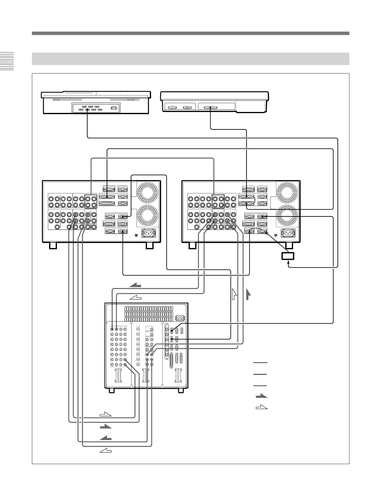
DVS-6000/6000C Digital Video Switcher connections
System Configuration
K
V
V
K
V
K
K
V
K
V
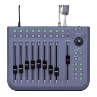
BKDS-6010 Switcher Control Panel
BKDM-3010 DME Control Panel
DME
PROCESSOR
25-pin remote cable
25-pin remote cable
COMBINER
INPUTS
DME-3000/7000
CONTROL
PANEL
AUX
DME-3000/
7000
COMBINER
OUTPUTS
CONTROL
PANEL
CONTROL
PANEL
AUX
DIGITAL
OUTPUTS
SWITCHER
PANEL
DIGITAL
INPUTS
PRIMARY
INPUTS
DIGITAL
OUTPUTS
DIGITAL
INPUTS
SWITCHER
PANEL
Conversion
connector
b)
DME 1
(AUX BUS)
DME 2
(AUX BUS)
AUX BUS
OUTPUTS 1, 2
PRIMARY
INPUTS
AUX BUS
OUTPUTS 3, 4
DVS-6000/6000C
Digital Video
Switcher
: Loop-through connection
: 9-pin remote cable
: 75-ohm coaxial cable
: Key signals
: Video signals
a)
c) c) c) c)
a) Component mode: Connect to VIDEO/Y, KEY/Z and Z
connectors using 3 cables.
Composite mode: Connect to VIDEO/Y, EXT/C, KEY/Z and Z
connectors using 4 cables.
b) Supplide with BKDS-6050 Key Frame Control Panel
c) These connectors are provided only on the DME-7000.